Optical receiver

a receiver and optical technology, applied in the field of optical receivers, can solve the problems of large dynamic range of photocurrent, difficult to accurately detect voltage across the resistor, and inability to meet the headroom requirements of the photodiode, and achieve the effect of improving the working point of the tia and sufficient sensitivity

Active Publication Date: 2011-06-16
NVIDIA DENMARK APS
View PDF5 Cites 1 Cited by
  • Summary
  • Abstract
  • Description
  • Claims
  • Application Information

AI Technical Summary

Benefits of technology

[0015]Similar to the first mention embodiment small currents may be measure across the first sensing resistor which may be arranged to be sufficiently large to render a sufficient sensitivity. Larger current may be measured in conjunction with the transimpedance amplifier connected to the second node of the photodiode. Transimpedance amplifiers (TIA) are in this field commonly applied in the detection of the AC signal. One function of the shunt circuit is to subtract the DC current (i.e. here referred to as the photocurrent) from the current from the photodiode. This improves the working point of the TIA. However, the shunt circuit may induce noise, so for small current the shunt circuit may in one embodiment be turned off. It is therefore beneficial to measure the current for small currents across the sensing resistor and for larger current use the current sensing circuit related to the shunt circuit.

Problems solved by technology

One challenge is that the photocurrent may have a large dynamic range.
For low current the voltage across the resistor may be difficult to detect accurate and for large current the headroom required by the photodiode may be violated.
However, the shunt circuit may induce noise, so for small current the shunt circuit may in one embodiment be turned off.

Method used


Image

  • Optical receiver
  • Optical receiver
  • Optical receiver

Examples


Embodiment Construction

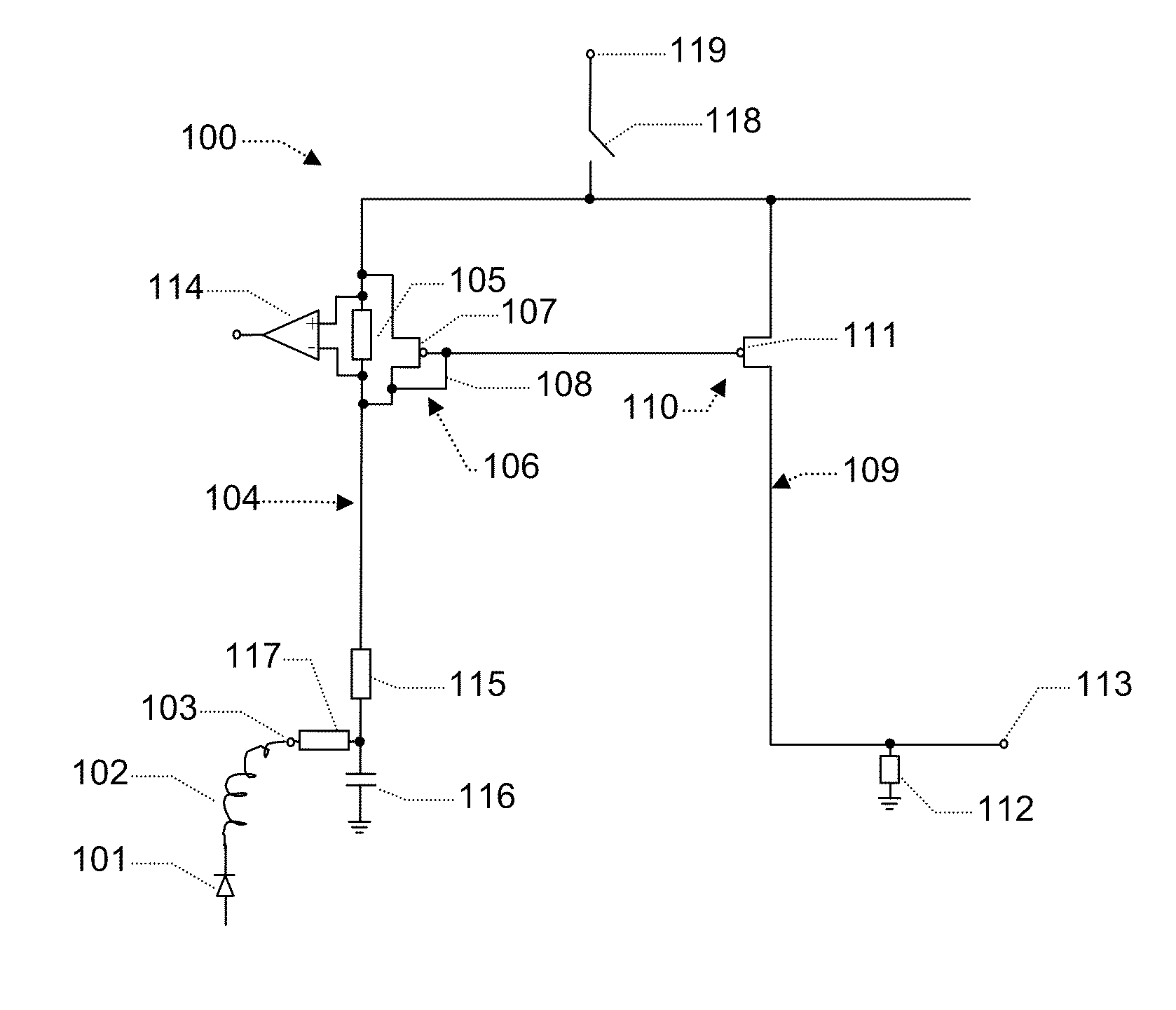
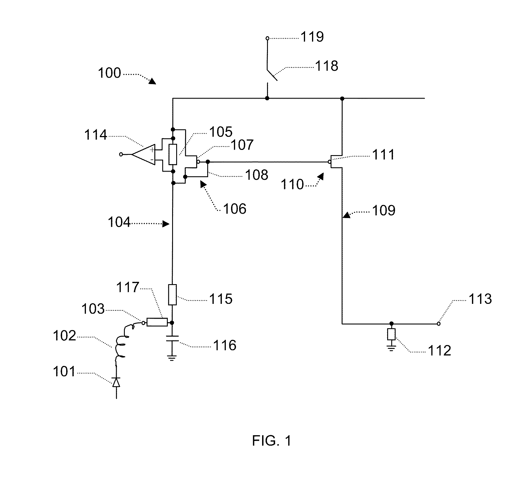
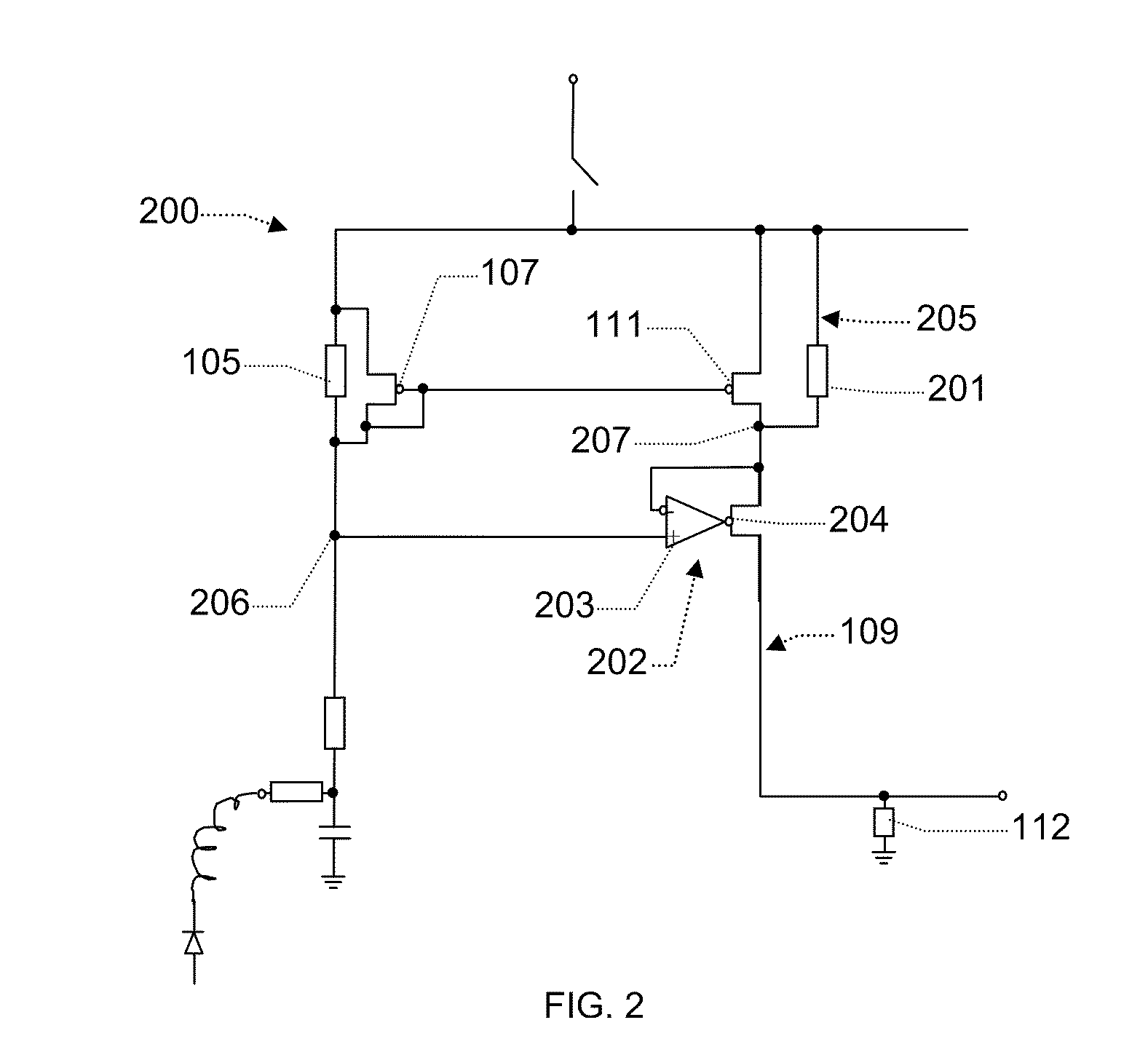
[0028]In one embodiment the first current path is connected with a secondary current path via a voltage controller circuit arranged to impose a voltage from the first branch to the secondary current path. In principle a voltage controller circuit may be any circuit suitable for imposing a voltage in the secondary branch. In this way a voltage related to the voltage across the first sensing resistor may in one embodiment be imposed onto a node of the second current path causing a response related to the current through the first sensing resistor. In one embodiment the secondary current path comprises a second sensing resistor. In one embodiment the imposed the voltage imposed by the voltage controller is arranged to produce a current in said secondary current path, such as a current reflecting the current in the first sensing resistor. In one embodiment the voltage determines the voltage across said second sensing resistor, in another embodiment the current in the second sensing resi...


PUM


Abstract

An optical receiver suitable for connecting to a photodiode generating a photocurrent with a sensing resistor and a diode circuit in parallel with the sensing resistor to limit the voltage across the sensing resistor. The diode circuit allows for a larger resistor providing greater sensitivity without risking violating the necessary headroom available to the photodiode.

Description

TECHNICAL FIELD The present invention relates to the field of optical receivers in particular integrated optical receivers.BACKGROUND ART[0001]In the art of optical communication the optical receiver often includes a function to provide an RSSI (Received Signal Strength Indication) signal and / or so-called LOS (Loss Of Signal) indicators or Squelch. The RSSI measurement generally provides a measure of the received DC signal which may be beneficial to allow active alignment between an optical fiber and the photodiode and / or to monitor the performance of the transmitter at the other end. The LOS (and / or Squelch) indicator may for example be used to indicate if the transmitter at the other end is present and / or whether the transmitter at the other end has become worn so that failure is eminent or already has occurred. In the optical receiver arranged to detect the current from a photodiode, the circuit detects an average of the photocurrent generated in the photodiode by inserting a res...

Claims


Application Information

Patent Timeline
Patent Type & Authority Applications(United States)
IPC IPC(8): G01J1/44
CPCG01J1/46
Inventor CHRISTENSEN, KENN
Owner NVIDIA DENMARK APS
Why Eureka
Try Eureka