
Wind Turbine With Improved Cooling

a wind turbine and cooling technology, applied in the direction of machines/engines, liquid fuel engines, electric generator control, etc., can solve the problems of environmental pollution, blockage, clogging and blocking of air heat exchanges, etc., and achieve the effect of increasing improving the cooling effect of the nacell

Inactive Publication Date: 2011-06-16
WINTER CURT B
View PDF19 Cites 13 Cited by
  • Summary
  • Abstract
  • Description
  • Claims
  • Application Information

AI Technical Summary

Benefits of technology

[0010]The advantages of the invention include the fact that no high salt content or humid air comes into contact with the wind turbine components, such as generators, brakes, bearings and electronics. The risk of corrosion is thus drastically reduced within the nacelle and the tower. The nacelle is a housing that contains components, such as the generator, brakes, bearing assembly, gear boxes, electronics and controls. The nacelle also includes a reservoir for retaining cooling fluid. Preferably, a plurality of internal cooling fins extend from an inner surface of the nacelle into reservoir chambers formed in the nacelle for extracting heat from the cooling liquid. Heat is transferred from the plurality of internal cooling fins to an outer surface area of the nacelle to be cooled by atmosphere wind.
[0013]For improving the cooling effect of the nacelle, the nacelle can be completely or partially made out of metal. It is preferable to use aluminum as the metal in order to also take advantage of the cooling effect of an outer surface area of the nacelle, which is constantly enveloped by wind, and thus to increase the wind turbine cooling. The outer surface area of the nacelle is cooled by atmospheric wind.

Problems solved by technology

This is particularly disadvantageous if the outside air is humid or, particularly in coastal regions, if it has a high salt content, and the cooling elements are then exposed to this humid and high salt content air.
This problem is especially extreme with wind energy facilities that stand directly on a coast or, in offshore technology, directly in salt water.
Another problem is the environmental contamination of air heat exchanges being clogged and blocked.

Method used


Image

  • Wind Turbine With Improved Cooling
  • Wind Turbine With Improved Cooling
  • Wind Turbine With Improved Cooling

Examples


Embodiment Construction

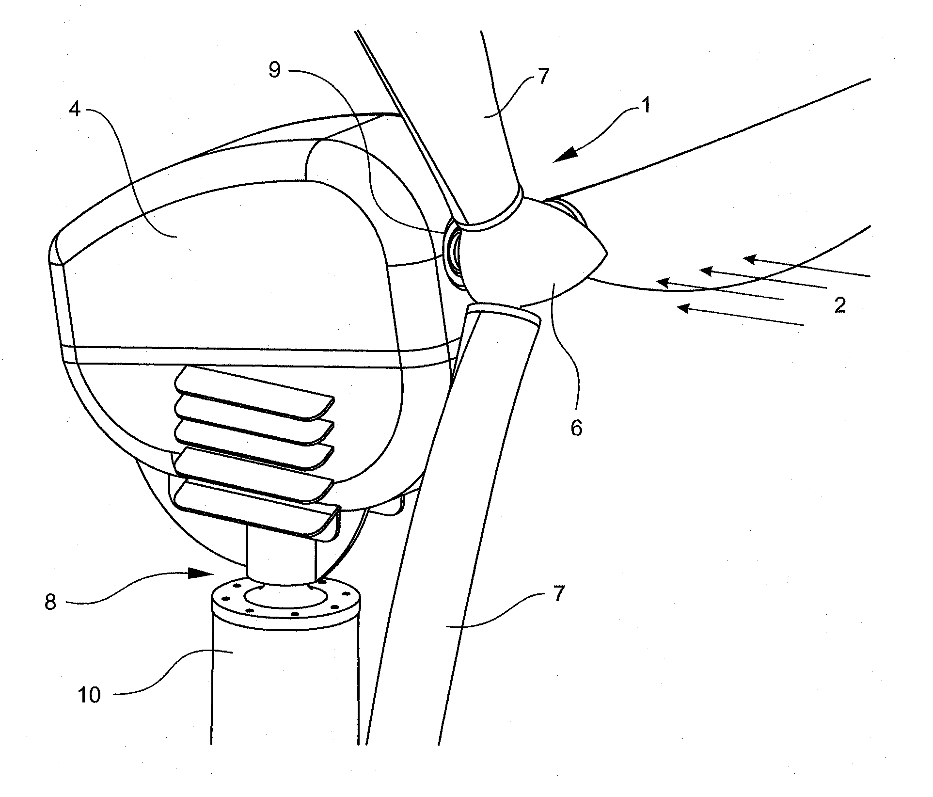
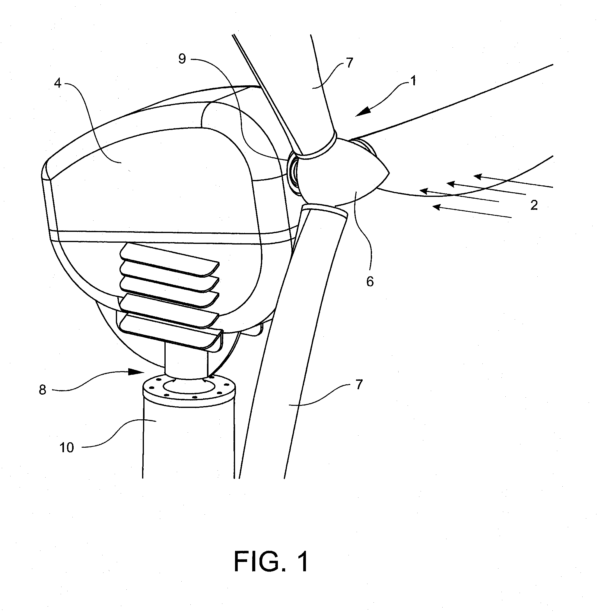
[0021]With reference now to the drawings, and particularly to FIG. 1, there is shown a side view of a wind turbine 1. The wind turbine 1 preferably includes a nacelle 4, a rotor 6, a pivot system 8 and a tower 10. The nacelle 4 is pivotally retained on a top of the tower10 with the pivot system 8. A bottom portion of the tower 10 is anchored in the ground (not shown). The nacelle 4 houses a rotor drive shaft, generator and other components of the wind turbine 1. The components found in the nacelle 4 are well known in the art and need not be shown or explained in detail. The rotor 6 extends from an end of a rotor drive shaft 9. The rotor 6 includes a plurality of blades 7 and the rotor drive shaft 9.

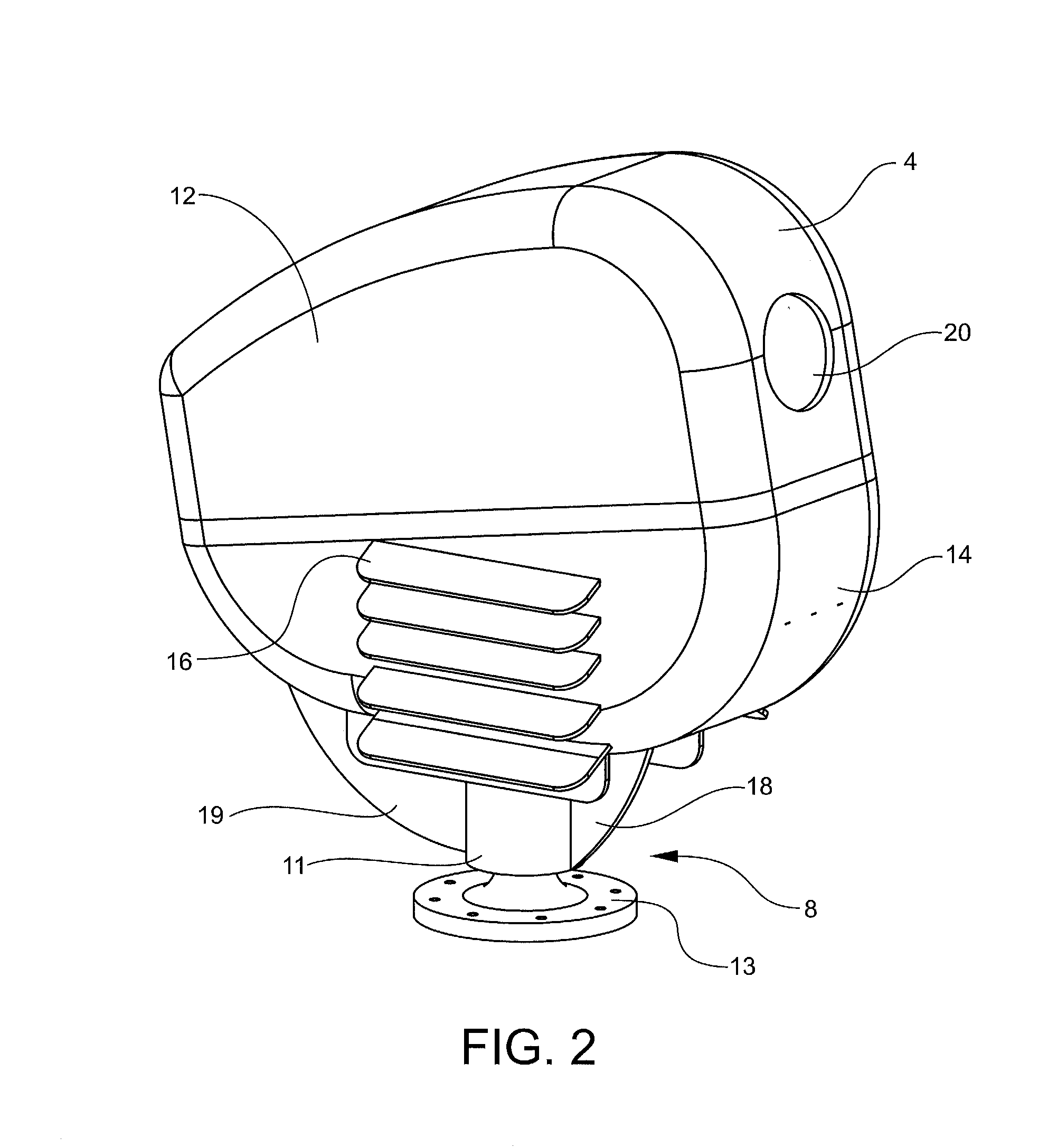
[0022]With reference to FIGS. 2-3, the nacelle 4 includes a shaft housing 12, a reservoir housing 14 and a plurality of external cooling fins 16. The shaft housing 12 may be secured to the reservoir housing 14 with any suitable method. The rotor drive shaft 9 is inserted through a drive s...


PUM


Abstract

A wind turbine with improved cooling, which provides liquid cooling for a wind turbine with a completely closed or at least partially closed cooling circuit, with which the heat to be dissipated from the cooling circuit is dissipated by a nacelle of the wind turbine. The wind turbine with improved cooling dissipates energy losses from heat and applied for the conversion of kinetic energy of wind into mechanical and electrical energy of the wind turbine.

Description

BACKGROUND OF THE INVENTION[0001]1. Field of the Invention[0002]The present invention relates generally to wind turbines and more specifically to a wind turbine with improved cooling, which provides improved cooling for components of the wind turbine.[0003]2. Discussion of the Prior Art[0004]Most wind turbines use heat transfer devices, such as fans to dissipate heat into the environment. In this way, cold air is suctioned in from the outside by the fans to cool wind turbine components such as the generator. The heated air is then blown back outside. Some wind turbines transfer component heat within a nacelle to a heat exchanger mounted external on the nacelle for atmosphere environment air to pass through and transfer the heat.[0005]All of these known solutions have in common a large amount of air that is always needed from the outside. This is particularly disadvantageous if the outside air is humid or, particularly in coastal regions, if it has a high salt content, and the coolin...

Claims


Application Information

Patent Timeline
Patent Type & Authority Applications(United States)
IPC IPC(8): F03D9/00
CPCF03D11/00F05B2240/14F05B2260/20Y10S415/908Y02E10/726Y02E10/722F05B2260/2241F03D80/60Y02E10/72Y02P80/10
Inventor WINTER, CURT B.
Owner WINTER CURT B
Learn More