LED driving circuit

a driving circuit and led technology, applied in the direction of electroluminescent light sources, electric lighting sources, semiconductor lamp usage, etc., can solve the problems of dimming circuit malfunction, high power loss, flicker or flash, etc., to reduce or prevent the malfunction of the dimming circuit, reduce or prevent the effect of high power loss

Active Publication Date: 2011-06-16
MINEBEAMITSUMI INC
View PDF7 Cites 43 Cited by
  • Summary
  • Abstract
  • Description
  • Claims
  • Application Information

AI Technical Summary

Benefits of technology

[0009]The present invention has been made in light of the problems described above, and it is an object of the present invention to provide an LED driving circuit having a simple circuit configuration and capable of reducing or preventing a malfunction of the dimming circuit, which is caused due to foreign noise or noise resulting from interference between the dimming circuits, without high power loss.
[0012]According to the above configuration, it is possible to provide an LED driving circuit having a simple circuit configuration and capable of reducing or preventing a malfunction of the dimming circuit, which is caused due to foreign noise or noise resulting from interference between the dimming circuits, without high power loss.

Problems solved by technology

However, the dimming device that performs the LED dimming with the conventional phase-controlled dimming circuit, which is described in JP-A-2009-26544, has the following problems.
Therefore, resulting from mismatch between the dimming circuit having the TRIAC and the LED illumination device, flicker or flash may occur.
Therefore, the dimming circuit may malfunction due to foreign noise or noise resulting from interference between the dimming circuits.
However, as the bleeder current flows, power loss in a bleeder circuit of the LED driving circuit increases and the temperature thereof increases largely.

Method used


Image

  • LED driving circuit
  • LED driving circuit
  • LED driving circuit

Examples


Embodiment Construction

[0016]Hereinafter, illustrative embodiments of the present invention will be described with reference to the drawings.

First Illustrative Embodiment

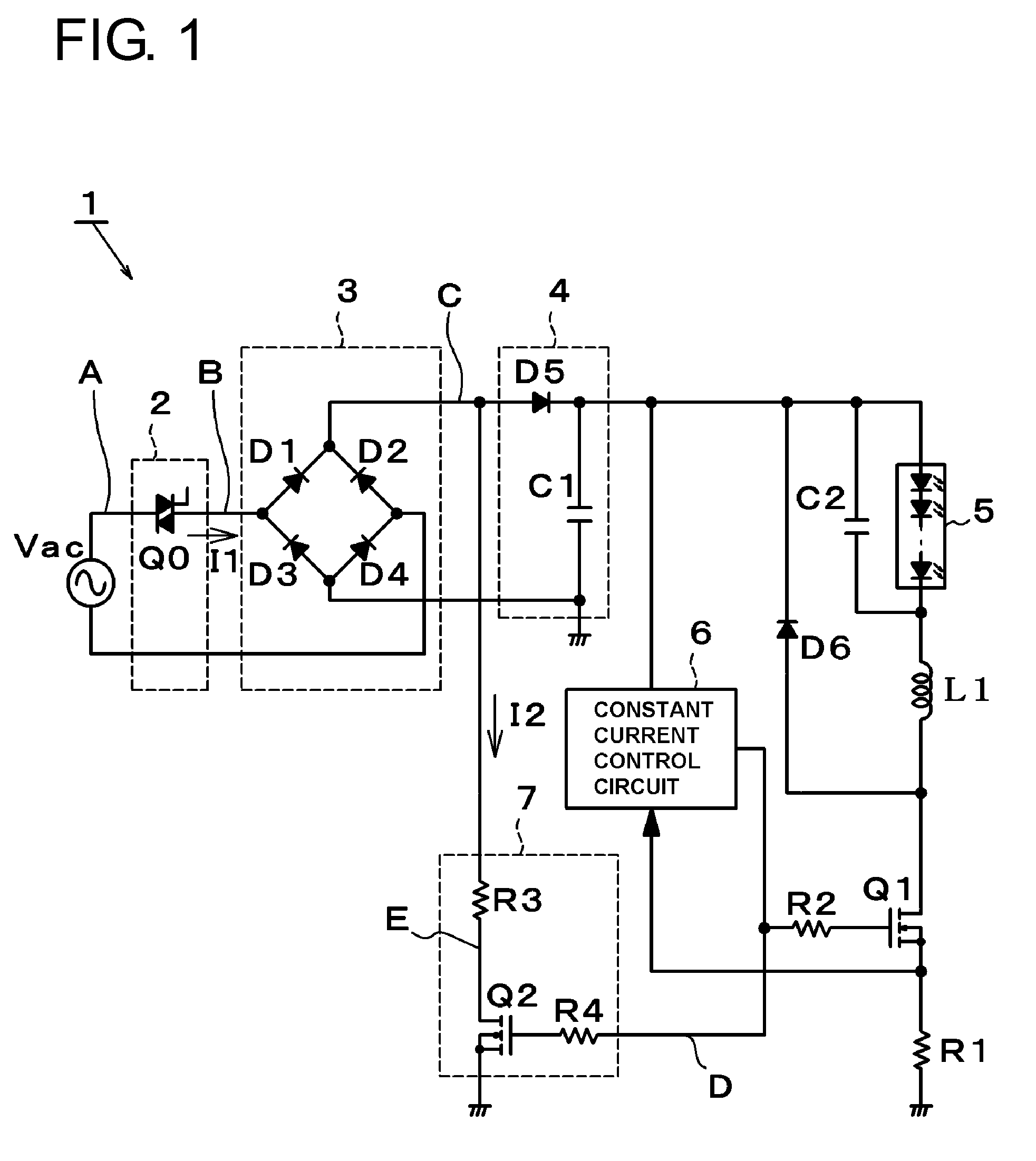
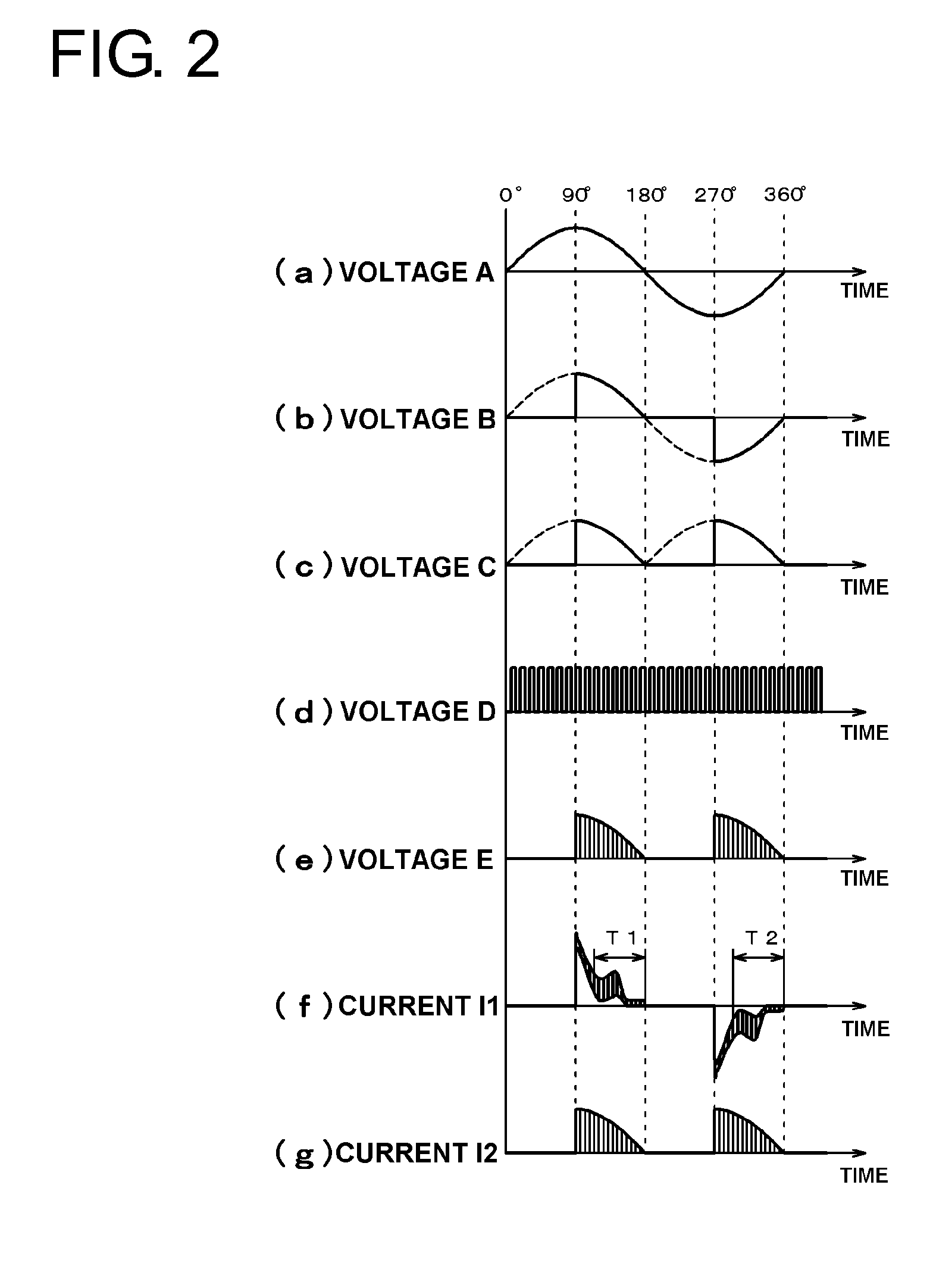
[0017]FIG. 1 is a circuit diagram of an LED driving circuit according to a first illustrative embodiment of the present invention, and (a) to (g) of FIG. 2 schematically show a voltage waveforms or a current waveforms of each point of the circuit shown in FIG. 1.

[0018]As shown in FIG. 1, an LED driving circuit 1 includes a dimming circuit 2 that controls a conducting angle of an alternating current supplied from a commercial alternating-current power supply Vac so as to phase-control a current to be supplied to a light emitting diode (LED) module 5, a rectifier circuit 3 that rectifies an alternating-current voltage output from the dimming circuit 2 and a smoothing circuit 4 that smoothes a direct current voltage output from the rectifier circuit 3, and drives the LED module 5 that is a light source for illumination. The LED driving circu...


PUM


Abstract

An LED driving circuit includes a dimming circuit that controls a conducting angle of an alternating current supplied from a power supply to phase-control a current to be supplied to an LED, a rectifier circuit that rectifies an alternating-current voltage output from the dimming circuit, a smoothing circuit that smoothes a direct current voltage output from the rectifier circuit, a switching device that is connected with the LED in series; a constant current control circuit that outputs a high frequency pulse signal to the switching device to control the switching device, and a bleeder circuit that is provided between an output terminal of the rectifier circuit and a ground and that has a bleeder resistance and a bleeder switch connected in series. The high frequency pulse signal is input to the bleeder switch so that a bleeder current having a high frequency pulse form flows in the bleeder resistance.

Description

BACKGROUND OF THE INVENTION[0001]1. Field of the Invention[0002]The present invention relates to a light emitting diode (LED) driving circuit, and more specifically, to an LED driving circuit that uses a phase-controlled dimming circuit for constant current drive of an LED.[0003]2. Description of the Related Art[0004]Conventionally, in an illumination apparatus having an incandescent lamp as a light source for illumination, a phase-controlled dimming circuit has been widely used which uses a TRIAC (bidirectional thyrister) to perform a dimming operation. The dimming circuit includes a controller, and the controller controls a conducting angle of the TRIAC to change a duty ratio of a commercial alternating-current power supply voltage to be supplied to the dimming circuit. Accordingly, power to be supplied to the light source is changed, so that the dimming operation is performed.[0005]Recently, also in an illumination apparatus having an LED as a light source for illumination, a dim...

Claims


Application Information

Patent Timeline
Patent Type & Authority Applications(United States)
IPC IPC(8): H05B37/02H05B44/00
CPCH05B33/0809H05B45/3575Y02B20/30H05B45/3725
Inventor SUZUKI, SHINICHI
Owner MINEBEAMITSUMI INC
Why Eureka
Try Eureka