
Electro-optical device, electronic apparatus and projection display device

a technology of electronic equipment and display devices, applied in the direction of electric digital data processing, instruments, computing, etc., can solve the problems of poor display, inability to obtain smooth display, and inability to accurately monitor the temperature of liquid crystals

Active Publication Date: 2011-06-16
SEIKO EPSON CORP
View PDF7 Cites 5 Cited by
  • Summary
  • Abstract
  • Description
  • Claims
  • Application Information

AI Technical Summary

Benefits of technology

[0009]An advantage of some aspects of the invention is to provide an electro-optical device that can prevent occurrence of poor gray scale due to a temperature change, without subsequently attaching the temperature sensor in adopting a digital driving mode, and an electronic apparatus and a projection display device including the electro-optical device.
[0011]In the invention, the driving portion converts the image data into the digital driving signal at the data conversion portion and supplies it to the pixel electrode. Herein, the digital driving signal is made of ON-voltage in which the brightness of the pixel saturates and OFF-voltage in which the pixel becomes light-off state in each of a plurality of subfields into which a field period is divided on a time axis, and performs a gray scale display through a balance of the period at which the ON-voltage is applied and the period in which the OFF-voltage is applied, or a timing at which the ON-voltage is applied. But, in the case of the digital driving mode, if the behavior of the liquid crystal upon application of the ON-voltage varies depending on the temperature, a distortion of the gray scale occurs, but in the invention, because the temperature detection conductive film is provided on the element substrate, in this temperature detection conductive film the resistance varies depending on the temperature. In addition, the data conversion portion performs a correction corresponding to a change in resistance in the temperature detection conductive film when generating the digital driving signal. Accordingly, since the correction corresponding to this temperature change is performed even though the temperature of the element substrate is changed, a distortion of the gray scale does not occur and the poor display does not occur. Furthermore, the temperature detection conductive film is a conductive film doped with an impurity in the semiconductor layer. This semiconductor layer of the conductive film can be simultaneously formed with a semiconductor layer of the field effect transistor for switching the pixel, and also can accurately monitor the temperature of the liquid crystal. Thus, according to the invention, it is possible to suppress distortion of the gray scale due to the temperature change without subsequently attaching the temperature sensor to the element substrate.
[0012]The invention is effectively adapted to a case where the data conversion portion generates, as the digital driving signal, a signal in which the ON-voltage discontinuously appears. In the case of this digital driving mode, the effect of applying the invention is significant to the extent that the gray scale display is performed by making maximum use of a transitional phenomenon of an orientation change of a liquid crystal and to the extent that it is easily affected by temperature change.
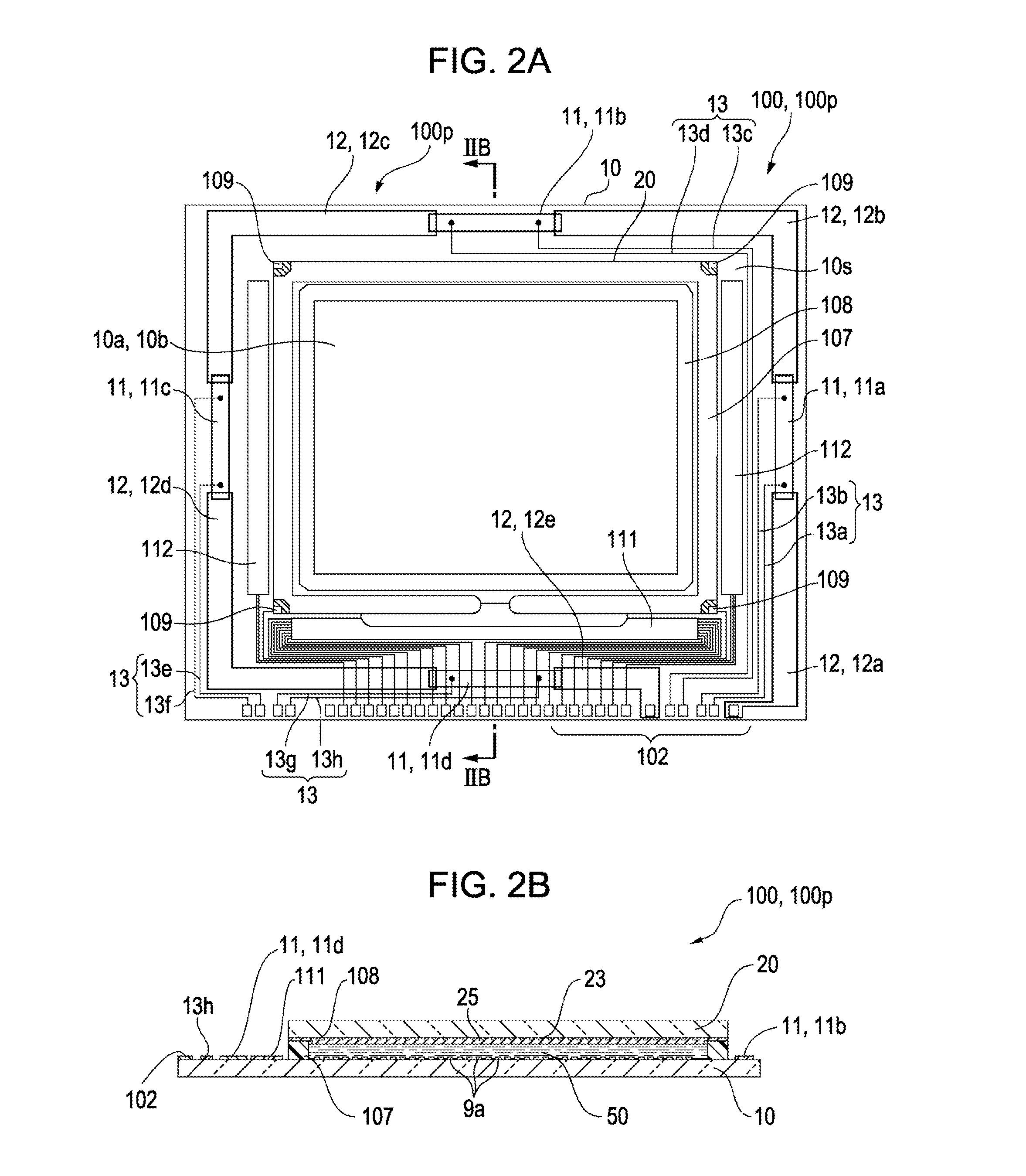
[0013]According to the invention, it is preferable to provide, on the element substrate, a wiring for applying an electric current electrically connected to each of two points separated in the longitudinal direction of the temperature detection conductive film, and a resistance detection wiring electrically connected to each of two points separated in the longitudinal direction of the temperature detection conductive film. According to this configuration, since the resistance can be monitored by a so-called four-terminal method, the resistance change can be accurately monitored, and thus it is possible to appropriately perform a temperature correction for the digital driving signal.
[0016]According to the invention, it is preferable that on the element substrate, a high thermal conductivity insulating film is continuously formed from a pixel portion on which a plurality of the pixels is arranged to a region on which the temperature detection conductive film is formed, wherein the high thermal conductivity insulating film has a higher thermal conductivity than an interlayer insulating film formed on the pixel portion. According to this configuration, since a temperature of the entire element substrate can be uniformized, even when the pixel and the temperature detection conductive film are separated, it is possible to accurately monitor the temperature of the pixel.
[0018]The electro-optical device according to the invention can be used in a projection display device (an electronic apparatus), and in this case, the projection display device includes a light source portion for supplying an illumination light to the electro-optical device, and a projection lens system that projects a modulated illumination light after the illumination light is modulated by the electro-optical device. In the case of the projection display device, since the illumination light of the high brightness from the light source portion is irradiated to the electro-optical device, the effect of the case according to the invention is significant to the extent that it is easy for the temperature change in the element substrate to occur.

Problems solved by technology

Thereby, in the case of using the digital driving mode described above, if the temperature of the liquid crystal panel changes, it distorts the gradation property of a displayed image and causes occurrence of poor display.
For example, if the temperature change in an atmosphere provided with the projection display device, or the amount of an illumination light supplied from a high brightness lamp to the liquid crystal device is adjusted using a diaphragm or the like depending on the displayed image, as the result of the occurrence of temperature change in the liquid crystal panel and a distortion of the gray scale, it is impossible to obtain a smooth display due to occurrence of a display unevenness or the like.
On the other hand, if a temperature sensor is subsequently attached in the vicinity of the element substrate, there is a problem in that the liquid crystal temperature cannot be accurately monitored due to separation of the temperature sensor from the liquid crystal as well as cost increases.

Method used


Image

  • Electro-optical device, electronic apparatus and projection display device
  • Electro-optical device, electronic apparatus and projection display device
  • Electro-optical device, electronic apparatus and projection display device

Examples


Embodiment Construction

[0034]Hereafter, embodiments of the invention will be described with reference to the drawings. Also, in drawings referred to hereafter in the description, to the extent that each layer or each member can be recognized in the drawings, each layer or each member is shown at different scales.

Configuration of Electro-Optical Device

Overall Configuration of Electro-Optical Device

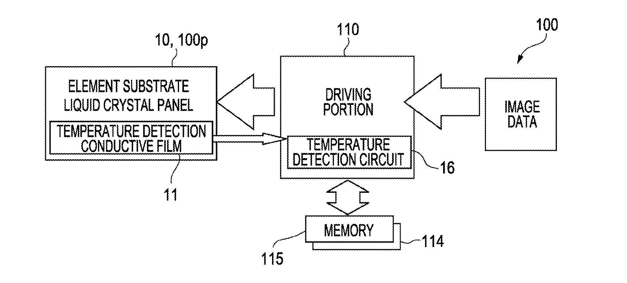
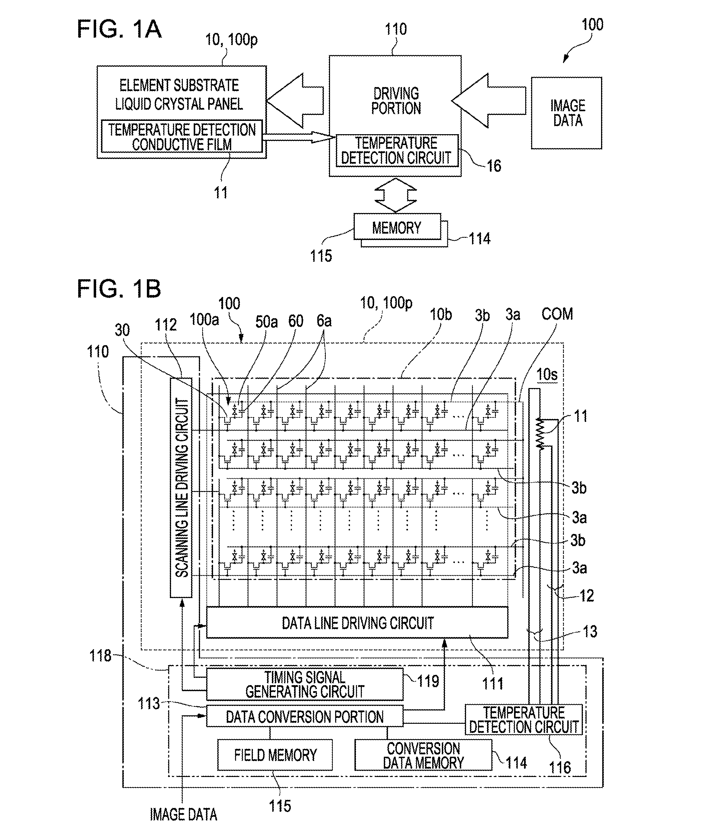
[0035]FIGS. 1A and 1B are an explanatory view showing an overall configuration of an electro-optical device according to the invention and FIG. 1A is a block view schematically showing an electrical configuration of the electro-optical device, and FIG. 1B is a block view showing in detail the electrical configuration of the electro-optical device.

[0036]As shown in FIG. 1A, the electro-optical device of this embodiment is a liquid crystal device, and includes a liquid crystal panel 100p, and a driving portion 110 for driving the liquid crystal panel 100p based on image data supplied externally.

[0037]As shown in FI...


PUM


Abstract

An electro-optical device includes an element substrate having a temperature detection conductive film formed by doping with an impurity in the same semiconductor layer as a semiconductor layer of transistor; and a driving portion for supplying a driving signal, wherein the driving portion includes a data conversion portion for converting image data and generating, as the driving signal, a digital driving signal made of an ON-voltage in which the brightness of the pixel is saturated and an OFF-voltage in which the pixel becomes a light-off state in each of a plurality of subfields in which a field period is divided on a time axis, and the data conversion portion performs a correction corresponding to a change in resistance in the temperature detection conductive film when generating the digital driving signal.

Description

[0001]Japanese Patent Application No. 2009-283742, filed Dec. 15, 2009 is incorporated by reference in its entirety herein.BACKGROUND[0002]1. Technical Field[0003]The present invention relates to an electro-optical device for emitting a light modulated in a condition which is associated with an electrical signal, and an electronic apparatus and a projection display device including the electro-optical device.[0004]2. Related Art[0005]In a projection display device called a projector or the like, a liquid crystal device used as a light valve is constituted as an electro-optical device for emitting a light modulated in a condition which is associated with an electrical signal. Among the electro-optical devices, in a case of a transmissive liquid crystal device, a liquid crystal panel receives light entering from one surface, spatially modulates this light, and emits the modulated light from another surface. On the other hand, in a case of a reflective liquid crystal device, the liquid...

Claims


Application Information

Patent Timeline
IPC IPC(8): G09G5/10
CPCG02F2203/60G09G3/2022G09G2320/041G09G2320/0285G09G3/3648
Inventor HIROSHIMA, YASUSHI
Owner SEIKO EPSON CORP
Learn More