
Method for manufacture of a package for the transport and/or storage of nuclear material, using the phenomenon of welding shrinkage

Inactive Publication Date: 2011-06-16
TN INT (FR)
View PDF21 Cites 0 Cited by
  • Summary
  • Abstract
  • Description
  • Claims
  • Application Information

AI Technical Summary

Benefits of technology

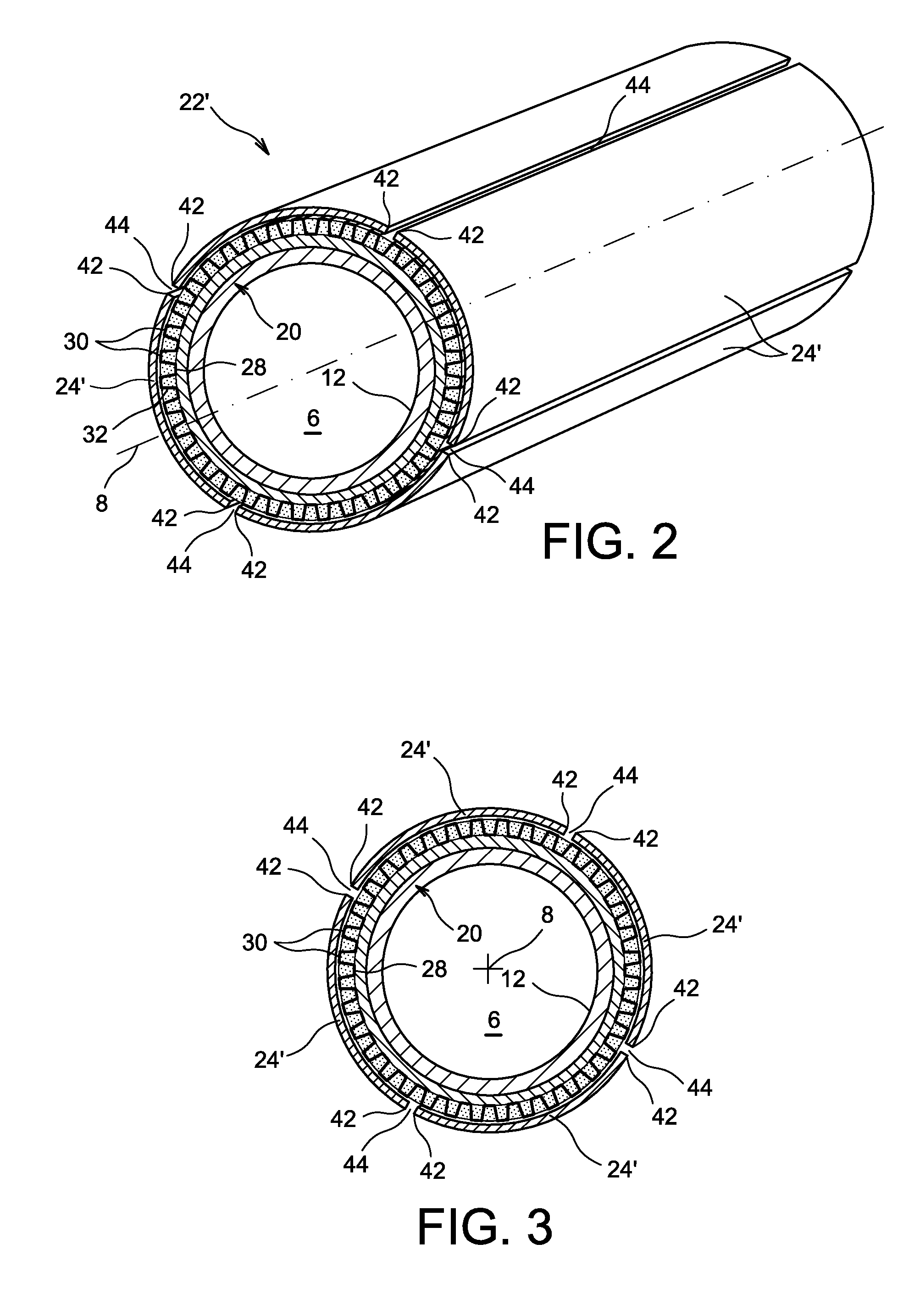
[0016]Thus, the invention makes use of the phenomenon of welding shrinkage, which is put to use to obtain the contact, or increase the intensity of this contact of the means of thermal conduction with the two ferrules, in the radial direction. In other words, the operation of assembly by welding allows, as a consequence of the welding shrinkage, a reduction of the perimeter of the casing designed to form the outer ferrule to be obtained, leading to a radial compression of the means of thermal conduction in the inter-ferrule space. This procedure leads to an essentially uniform radial stress of the means of thermal conduction between the two ferrules, in the circumferential direction, giving satisfactory contact along the length of the latter.
[0017]The principal benefit of this method lies in the simplicity of implementation and the short manufacturing time since, unlike the solution presented in document EP-A1-0 741 628, the number of angular sector(s) forming the casing is not conditional in any way on the number of thermal conduction elements extending radially in the inter-ferrule space, and this latter number can, indeed, be substantially higher. Here, it is stipulated that the angular sector(s) must be included as the constituent elements of the casing, defining the lengthways slits.
[0024]During the welding shrinkage observed during the assembly step, a relative movement is created in the circumferential direction between the inner surface of the casing and the thermal conduction elements. The advantageous consequence of the fact that each welding bead linking two edges is not fastened on to the means of thermal conduction is that it does not excessively constrain the latter in the circumferential direction, thus preventing damaging the means of radiological protection which may be installed between these means of thermal conduction. The said means of thermal conduction are preferably chosen such that they have first parts of contact intended to be in contact with the inner ferrule, and second parts of contact intended to be in contact with the outer ferrule, where the said first and second parts are arranged in alternating fashion in the circumferential direction, with each second part of contact linked to the first two parts of contact being directly consecutive to it, using respectively two joining parts.
[0037]As was explained above, during the welding shrinkage observed during the assembly step, a relative movement is created in the circumferential direction between the inner surface of the casing and some or all of the second parts of contact supported on this surface, and this movement therefore results from the reduction of the diameter in the casing designed to form the outer ferrule, after welding shrinkage. This movement ensures that the means of thermal conduction are not excessively constrained in the circumferential direction, notably with a view to preventing damaging the means of radiological protection, which are preferably arranged in the patterns of the means of thermal conduction.
[0039]Finally, given that each angular sector also preferably has an outer surface shaped like the arc of a circle in its transverse section, it is consequently easy to manufacture such sectors, of constant thickness, for example through a simple and inexpensive technique seeking to shape, using an appropriate tool, an initially flat sheet of metal, in order to obtain the desired arc-shaped sector.

Problems solved by technology

The installation of these means of thermal conduction in the course of the method of manufacture of the package is often lengthy and difficult, and as a consequence relatively expensive.
Since the number of thermal conduction ribs is generally very high, able to reach, for example, several tens, the method of manufacture of the package is therefore greatly hindered, in terms of assembly time, by the installation and welding of the many sectors forming the outer ferrule which holds in place, by clamping, the thermal conduction ribs.
Moreover, the package manufacturing time is hindered further by the machining on the lengthways edges of the ferrule sectors, intended to form the recesses gripping the outer radial ends of the thermal conduction ribs.
Lastly, the performance of a package obtained in this manner, in terms of heat evacuation, is limited.

Method used


Image

  • Method for manufacture of a package for the transport and/or storage of nuclear material, using the phenomenon of welding shrinkage
  • Method for manufacture of a package for the transport and/or storage of nuclear material, using the phenomenon of welding shrinkage
  • Method for manufacture of a package for the transport and/or storage of nuclear material, using the phenomenon of welding shrinkage

Examples


Embodiment Construction

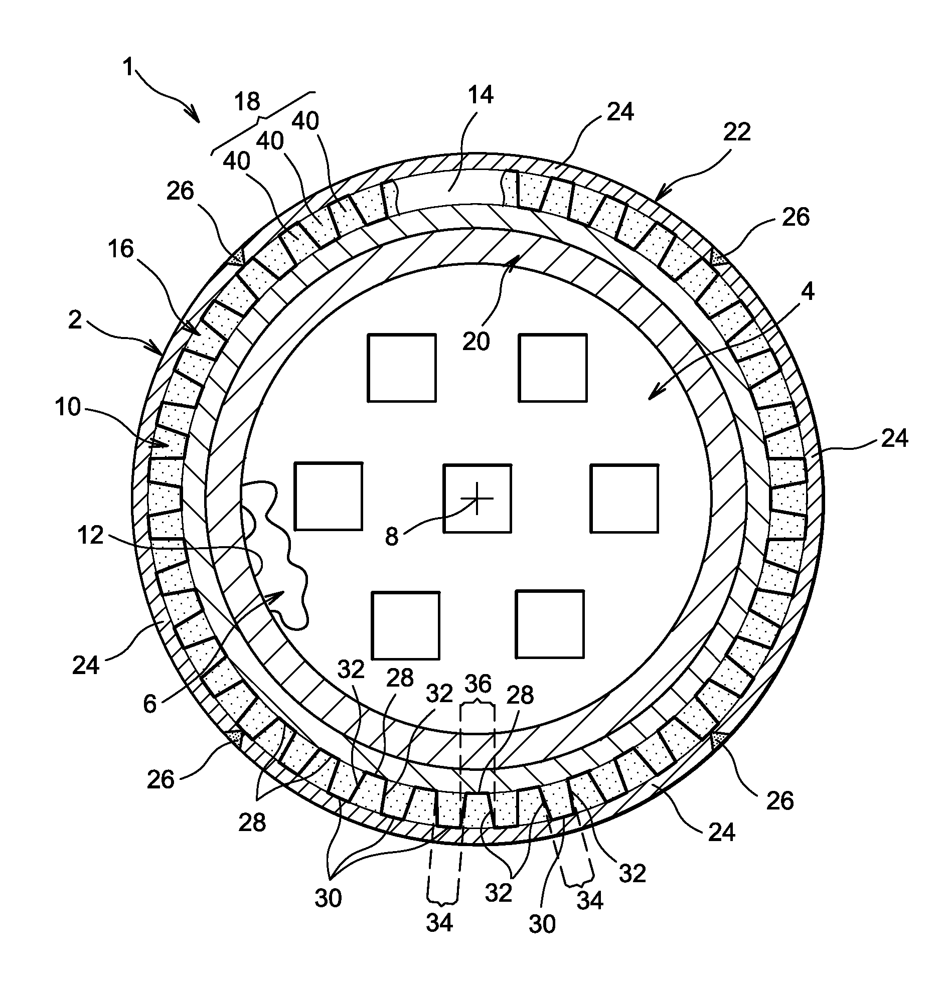
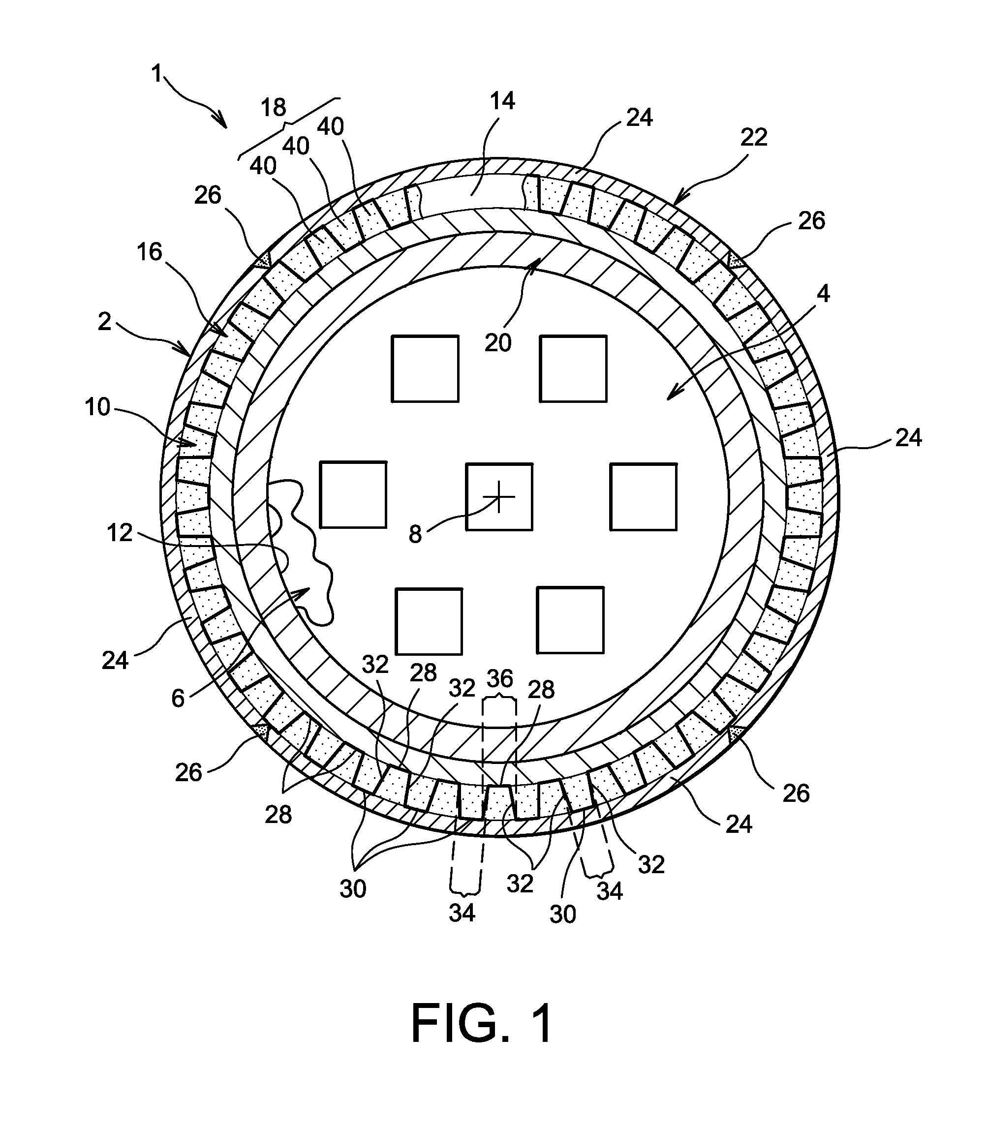
[0048]Firstly, with reference to FIG. 1, a container 1 for the transport and / or storage of assemblies of nuclear fuel can be seen. It is with this regard recalled that the invention is not limited in any way to the transport / storage of this type of nuclear material. As an example, the invention can also be applied to the transport / storage of PuO2 powder.

[0049]Container 1 comprises globally a package 2 forming the subject of the present invention, inside which is a storage device 4, also called a storage basket. Device 4 is designed to be positioned in a receptacle cavity 6 of package 2, as is shown schematically in FIG. 1, where it is also possible to note the lengthways axis 8 of this package, merged with the lengthways axes of the storage device and the receptacle cavity.

[0050]Throughout the disclosure the term “lengthways” must be understood as being parallel to the lengthways axis 8 and to the lengthways direction of the package, and the term “transverse” must be understood as b...


PUM


Abstract

A method for the manufacture of a package for the transport and / or storage of nuclear materials, where the package includes an inner ferrule, an outerferrule and means of thermal conduction, and where the method includes: the construction of an essentially circular casing having at least one lengthways slit defined by two facing lengthways edges; and the welding of the facing lengthways edges, in order to obtain the outer ferrule, where this step is accomplished such that the welding shrinkage causes a compression stress of the means of thermal conduction between the ferrules, in a radial direction, and such that each welding bead only fastens the two edges which it links one on to the other.

Description

DISCLOSURE[0001]1. Technical Field[0002]The present invention relates generally to the field of the manufacture of packages for the transport and / or storage of nuclear material.[0003]In particular, the invention concerns a method for manufacture of a package for the transport and / or storage of nuclear materials, including an inner ferrule, an outer ferrule and also means for thermal conduction in contact with both the inner and outer ferrules.[0004]2. State of the Prior Art[0005]Traditionally, for the transport and / or storage of nuclear materials, storage devices, also called storage “baskets” or “racks”, are used. These storage devices, habitually cylindrical in shape and essentially circular in section, are suitable for receiving nuclear materials. The storage device is intended to be housed in the cavity of a package in order to form jointly with the latter a container for the transport and / or storage of nuclear materials, in which they are completely confined.[0006]The abovement...

Claims


Application Information

Patent Timeline
IPC IPC(8): B21D51/26
CPCG21F5/10G21F5/008
Inventor BONNET, GILLESFONTANET, CELINELABORDE, JULIEN
Owner TN INT (FR)
Learn More