
Coulomb damping features using ultrasonic welding

a technology of ultrasonic welding and damping features, which is applied in the field of damping vibrations, can solve the problems of reducing fatigue life, distressing noise to users of vehicles or other objects, etc., and achieves the effect of increasing the damping

Active Publication Date: 2011-06-16
GM GLOBAL TECH OPERATIONS LLC
View PDF9 Cites 14 Cited by
  • Summary
  • Abstract
  • Description
  • Claims
  • Application Information

AI Technical Summary

Benefits of technology

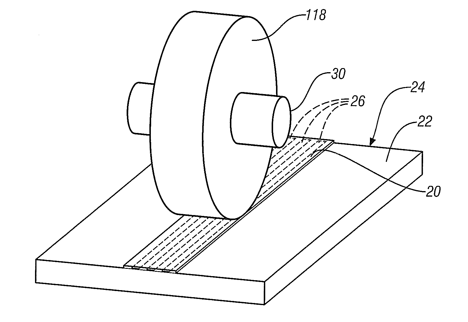
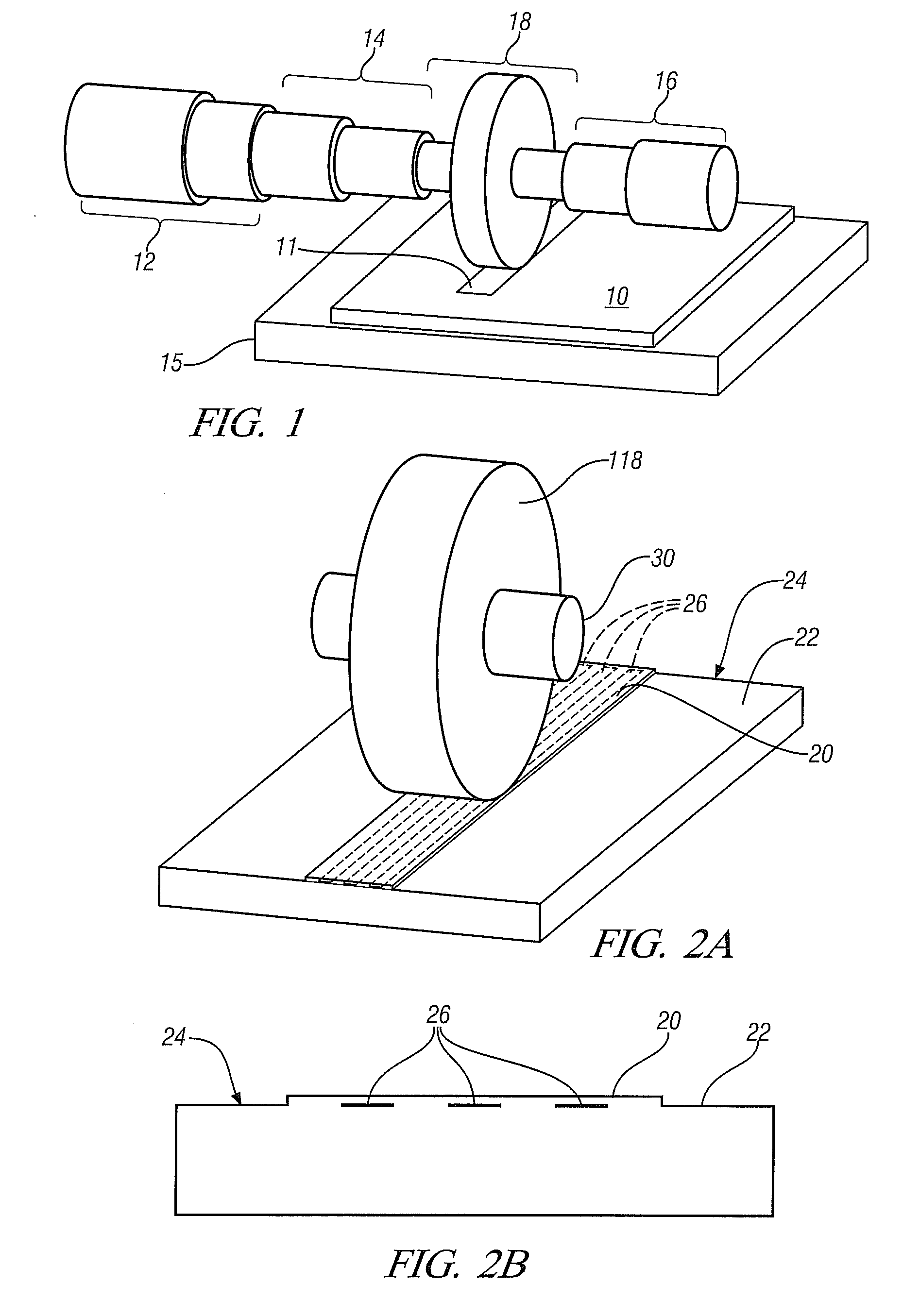
Thus, in some practices of this invention, the area of the damping interfaces within the manufactured article is determined or maximized to provide the necessary vibration damping effect for the article. (The added damping interfaces could be located at an anti-node of the normal vibration modes of the article structure.) The added material layer (and / or the surface of the article) is prepared with just enough bonding regions to suitably fix the material layer to the surface of the article in view of the mode of operation of the article. And the added layer is provided with regions that are oxidized, roughened, or provided with other coatings such that these un-weldable regions closely engage the underlying article surface in vibration-damping frictional contact. The ultrasonic welding process is conducted so as to retain these treated regions in an un-welded vibration-damping state. The frictional force could be further enhanced, increasing vibration damping, by judiciously applying heating or cooling during manufacture or by choice of materials with suitable coefficients of thermal expansion so that the strip material is held against the body of the article by residual stresses at the operating temperature of the body.
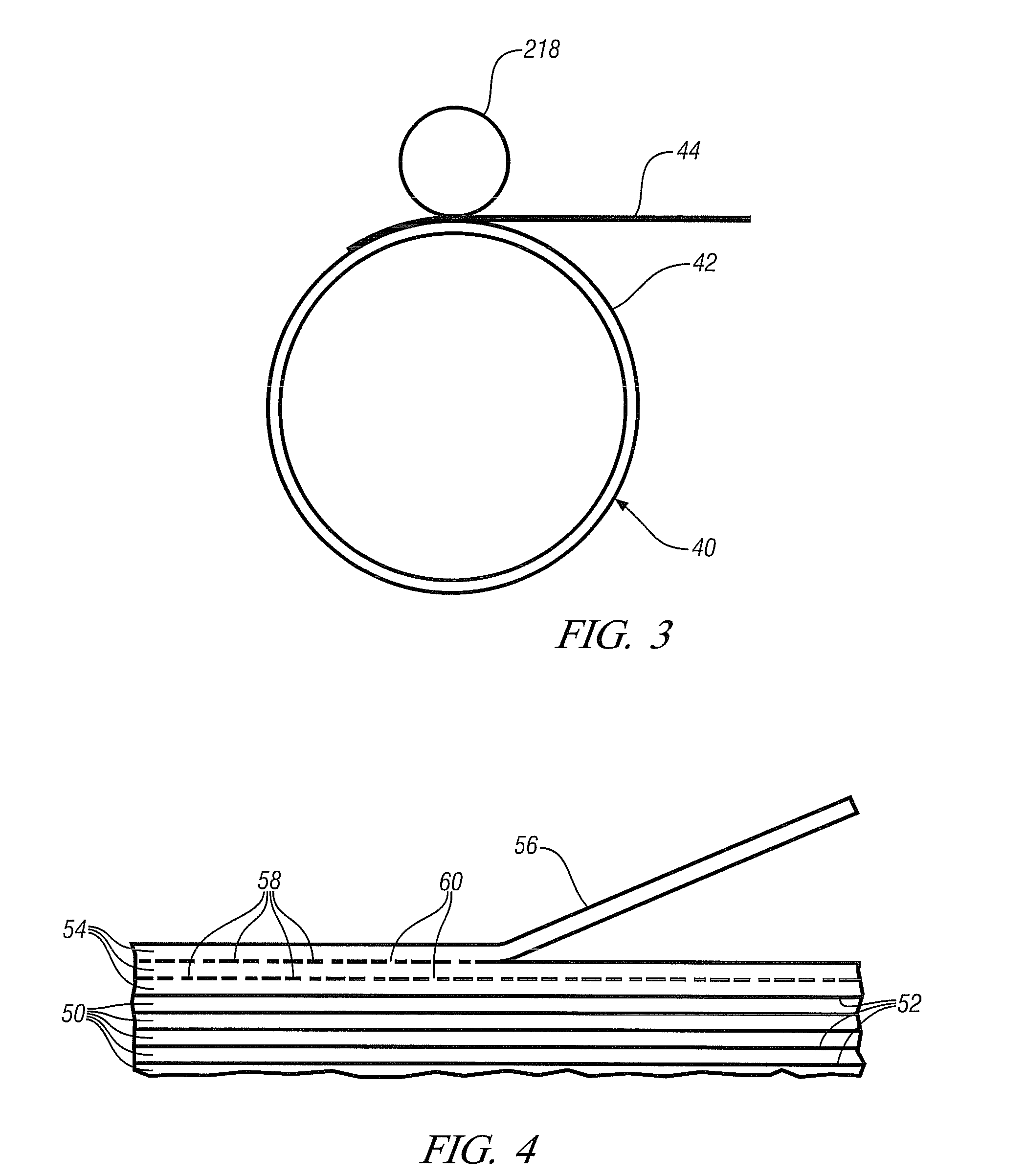
In yet another embodiment of the invention, multiple layers of added strip or foil could be applied to increase the damping effect, even up to forming entire components, or portions of components, out of the layered material-having multiple interfaces with bonded and un-bonded regions between them.

Problems solved by technology

Often such operational or imposed vibrations are of a frequency that, if coupled with the surrounding atmosphere in a manner that makes them audible, can produce distressing noise to a user of the vehicle or other article.
Further, vibrations in structures may lead to decreased fatigue life, if the amplitude, frequency, and mode structure are not controlled.

Method used


Image

  • Coulomb damping features using ultrasonic welding
  • Coulomb damping features using ultrasonic welding
  • Coulomb damping features using ultrasonic welding

Examples


Embodiment Construction

This invention uses ultrasonic welding to bond selected surface regions of a foil, tape, or strip to a surface of an article for the purpose of providing friction damping interfaces between the incompletely bonded strip and the adjacent surface of the article. These friction damping interfaces are formed in vibratile elements or portions of an article that are determined to be potentially susceptible to producing or transmitting unwanted vibrations. In other embodiments of the invention vibration absorbing elements of an article or entire articles may be Mimed by ultrasonic welding of successive layers of metal foil or sheets to build-up the vibration-absorbing article section or article. In this embodiment, non-welded regions are left between one or more of the layers of the layered structure to provide a desired number of friction damping interfaces.

In an illustrative embodiment of the invention, the article may be the aluminum alloy, cylindrical housing of an electric motor servi...


PUM

PropertyMeasurementUnit
thicknessaaaaaaaaaa
thicknessaaaaaaaaaa
frequencyaaaaaaaaaa

Abstract

Selected surface regions of coulomb vibration damping strips are bonded face-to-face by ultrasonic welding to a surface region of an article that may experience excessive vibration in use. In one embodiment, prior to welding, the intended facing side of the damping strip is treated to form surface regions that are oxidized, roughened, or coating so that the treated regions do not weld to the article surface. In another embodiment of the invention the ultrasonic welding process is controlled so as to produce regions (sometimes randomly interposed regions) of welded and non-welded regions between the damping strip and adjacent article surface. The unbonded regions of the otherwise welded strip lie in closely-spaced, interfacial, frictional contact with the adjacent article surface to damp vibration in the article. Other processes may be used for welding a damping strip to a surface of an article while leaving un-bonded, friction damping regions between regions of the damping strip and the facing surface of the article.

Description

TECHNICAL FIELDThis invention pertains to a practice of damping vibrations in an article by use of a thin layer or layers of like or suitable material that has a combination of surface regions welded to a surface on or within an article and un-bonded regions in frictional engagement with the adjacent surface. The bonded regions attach the layer to the adjacent surface and the un-bonded regions of the layer cause coulomb damping (frictional damping) of the adjacent portion of the article to reduce its production or transmission of vibrations.BACKGROUND OF THE INVENTIONAutomotive vehicle body structures, components, and propulsion devices are examples of many articles of manufacture that experience mechanical vibrations in their structure. The vibrations may, for example, occur in a wall or housing or partition structure, or in a shaft, or other structure susceptible to vibrating or passing vibrations. Often such operational or imposed vibrations are of a frequency that, if coupled wi...

Claims


Application Information

Patent Timeline
Patent Type & Authority Applications(United States)
IPC IPC(8): B32B15/01B23K20/10B23K31/02
CPCY10T428/12347B23K20/103
Inventor SCHROTH, JAMES G.PERRY, THOMAS A.
Owner GM GLOBAL TECH OPERATIONS LLC
Learn More