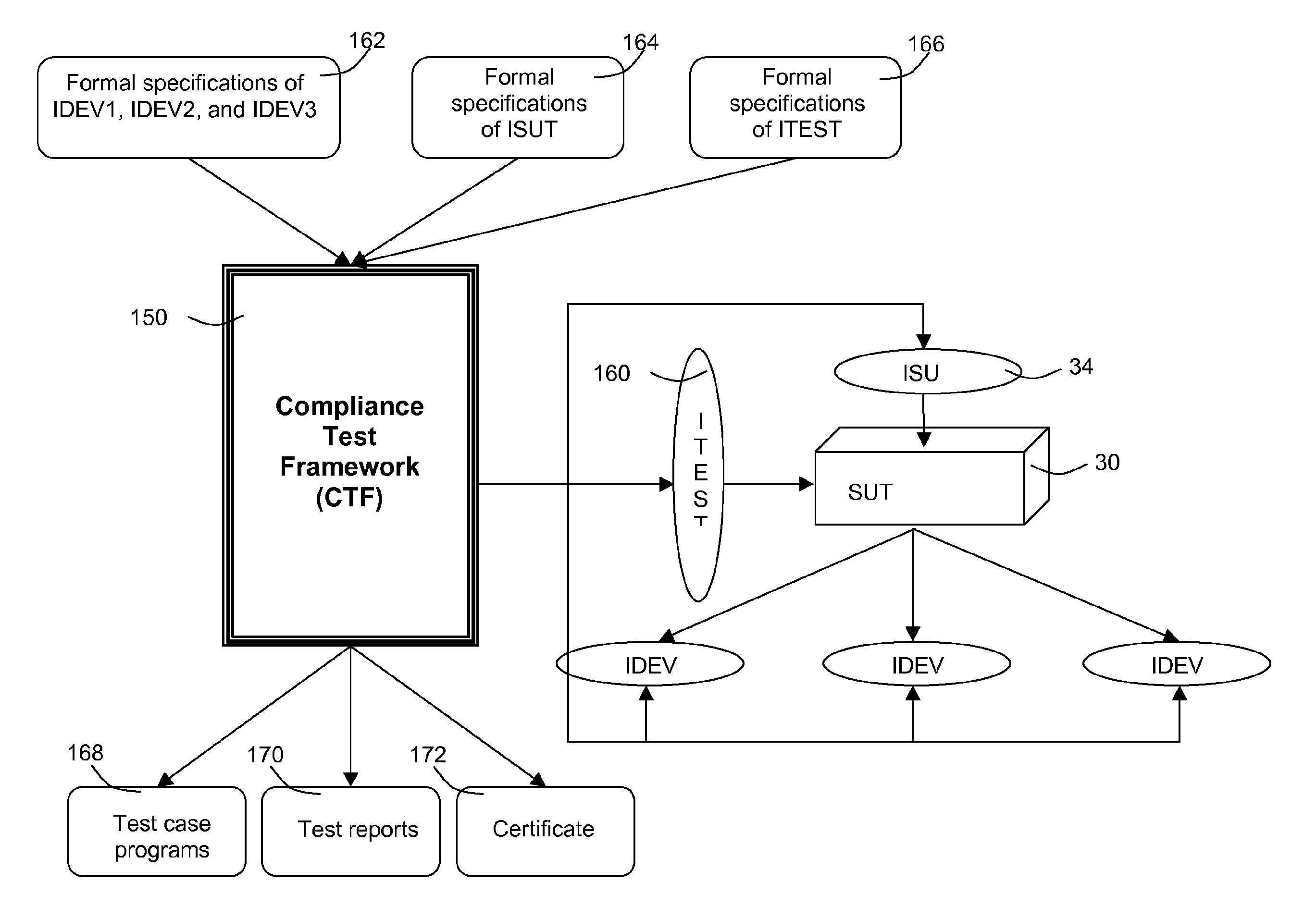
Alternatively, it is possible that errors may exist in the specifications as a result of errors introduced at conception of the design.
For example, a misunderstanding in the principles behind the specification (i.e. how a particular process is intended to function) could lead to an error by the software designer during the creation of the formal specifications.
Again, it is possible that errors may exist in the specifications or the SUT.
However, subtle complexities arise when dealing with communications from user interfaces to the SUT that are asynchronous, for example communications which are decoupled via a
queue.
However, this has two principle disadvantages in that it is frequently too complex to construct a usage model manually from the Input-
Queue test boundary 210 and it would be infeasible to do so using the standard SBS approach known from ASD.
However, this results in making the usage model unnecessary complex and large.
As such, any models using predicates are not suitable for direct input into JUMBL.
In practice, it is not feasible to achieve this transformation manually because it would take a disproportionate amount of time and is highly prone to errors.
Again, it is not feasible to achieve this transformation manually on an
industrial scale because it would take a disproportionate amount of time and is highly prone to errors.
However, Usage Models do not have this property and must therefore be transformed when converting them to TML Models.
However, real software systems are much more complex and have a far greater number of states and arcs.
As such, graphical models become too burdensome.
The probability of one stimulus occurring as opposed to any of the other possible stimuli occurring is generally not uniform.
If the expected response is not received within a defined time-out because the SUT gives no response at all or gives some other non-allowed response the SUT is at fault and the
test case fails.
However, it is not expected that there will be an additional allowed response in every case.
A problem arises when a non-deterministic choice arises out of design behaviour of the SUT, and it is possible to specify that a stimulus can result in two or more different responses.
However, it is not possible to predict which selection JUMBL will make in any given instance.
All internal behaviour of the SUT is both unknown and unknowable to the
test engineer and the tests.
Therefore, it has not previously been possible to prove the
correctness of a non-deterministic SUT by testing, irrespective of how many tests are executed.
All such
black box testing approaches present the following problems: the interfaces of the SUT which cross the test boundary may not be sufficient for testing purposes.
It is frequently the case that such interfaces designed to support the SUT in its operational context are insufficient for controlling the internal state and behaviour of the SUT and for retrieving data from the SUT about its state and behaviour, all of which is necessary for testing; and most systems exhibit non-deterministic behaviour when viewed as a black box.
For example, a
system may be commanded to operate a valve, and the system may carry out that task as instructed but there may be some exceptional failure condition that prevents the task being completed.
Thus, the SUT has more than one possible response to a command and it cannot be predicted nor controlled by the test environment which of the possible responses should be expected and constitutes a successful test.
Within current industrial testing practice, this non-deterministic behaviour presents a problem when designing tests; it is not possible to predict which of the possible set of non-deterministic responses will be emitted by the SUT.
This typically complicates
test design and increases the difficulty of interpreting test results.
An expert
Test Engineer is not expected to be skilled in the theory or practice of mathematically verifying software.
Therefore illegal events representing noncompliant SUT behaviour are immediately recognised and the test terminates in failure.
In this case, the test terminates in failure.
However, no statistical data is retained from the execution of these tests because the coverage
test set do not test functionality of the SUT sufficiently to result in statistically meaningful results.
However, if one or more Coverage Tests fail, either the Formal Specifications are incorrect, or the SUT is wrong.
If one or more tests fail, either the formal specifications are incorrect, or the SUT is wrong.
Again, test engineers can determine from the
test case failures whether the SUT behaviour is correct but one or more of the formal specifications is wrong.
Due to the number of interfaces, stimuli, and methods this is a non-trivial task, and when implemented manually is prone to errors and expensive.
It is, therefore, impossible to automatically generate the implementation of such
data validation functions; they must be programmed manually.
Since the data is specific to the SUT 30 it is also impossible to automatically generate the implementation of such data constructor functions; these must be programmed manually.
These calls will eventually result in decoupled calls from the test
router to the
test case.
When errors are detected, the SUT is repaired and this process invalidates the
statistical significance of the random test sets already used.
Previous test sets can be usefully re-executed as regression tests but when this is done, their statistical data is not added to the testing Chain when they are re-executed, as doing so would invalidate the measurements.
It is to be appreciated that a similar process / system which did not have the
Usage Model Verification step would not be useful.
Thus the Usage Models describing their behaviour are typically large and complex.
In practice, it is economically infeasible (if possible at all) to verify the
Usage Model by hand by inspection.
Without this
verification, statistical testing loses its validity.
In addition, if an alternative to JUMBL is to be used, it is conceivable that the
input format to such an alternative may not be TML.
However, none of these changes alter the basic principles of the inventions and a person skilled in the art will appreciate the variations which may be made.


