
Sintered valve guide and production method therefor

a valve guide and valve stem technology, applied in the direction of engine components, mechanical equipment, machines/engines, etc., can solve the problems of reducing the amount of lubricant supplied to the interface between the valve guide and the valve stem, and achieve the effect of improving wear resistance and producing as easily

Active Publication Date: 2011-06-23
RESONAC CORP
View PDF8 Cites 6 Cited by
  • Summary
  • Abstract
  • Description
  • Claims
  • Application Information

AI Technical Summary

Benefits of technology

[0005]In accordance with trends toward improving the performance and the fuel efficiency of automobile internal combustion engines in recent years, valve guides have been subjected to higher temperatures and higher pressures while internal combustion engines are running. Moreover, in view of recent environmental issues, amounts of lubricant supplied to an interface between a valve guide and a valve stem have decreased. Therefore, valve guides must withstand under more severe sliding conditions. In view of these circumstances, valve guides are required to have higher wear resistance, and thus wear resistance of sintered valve guides need to be further improved. Accordingly, an object of the present invention is to provide a sintered valve guide and a production method therefor, and the sintered valve guide has improved wear resistance compared with those of sintered valve guides disclosed in Japanese Examined Patent Publication No. 55-034858 and Japanese Patent Application of Laid-Open No. 4-157140.
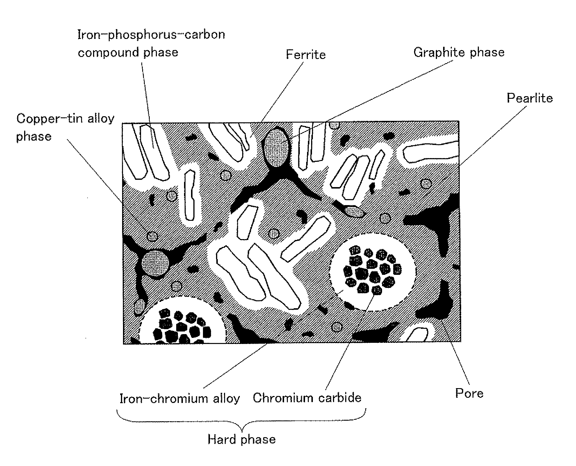
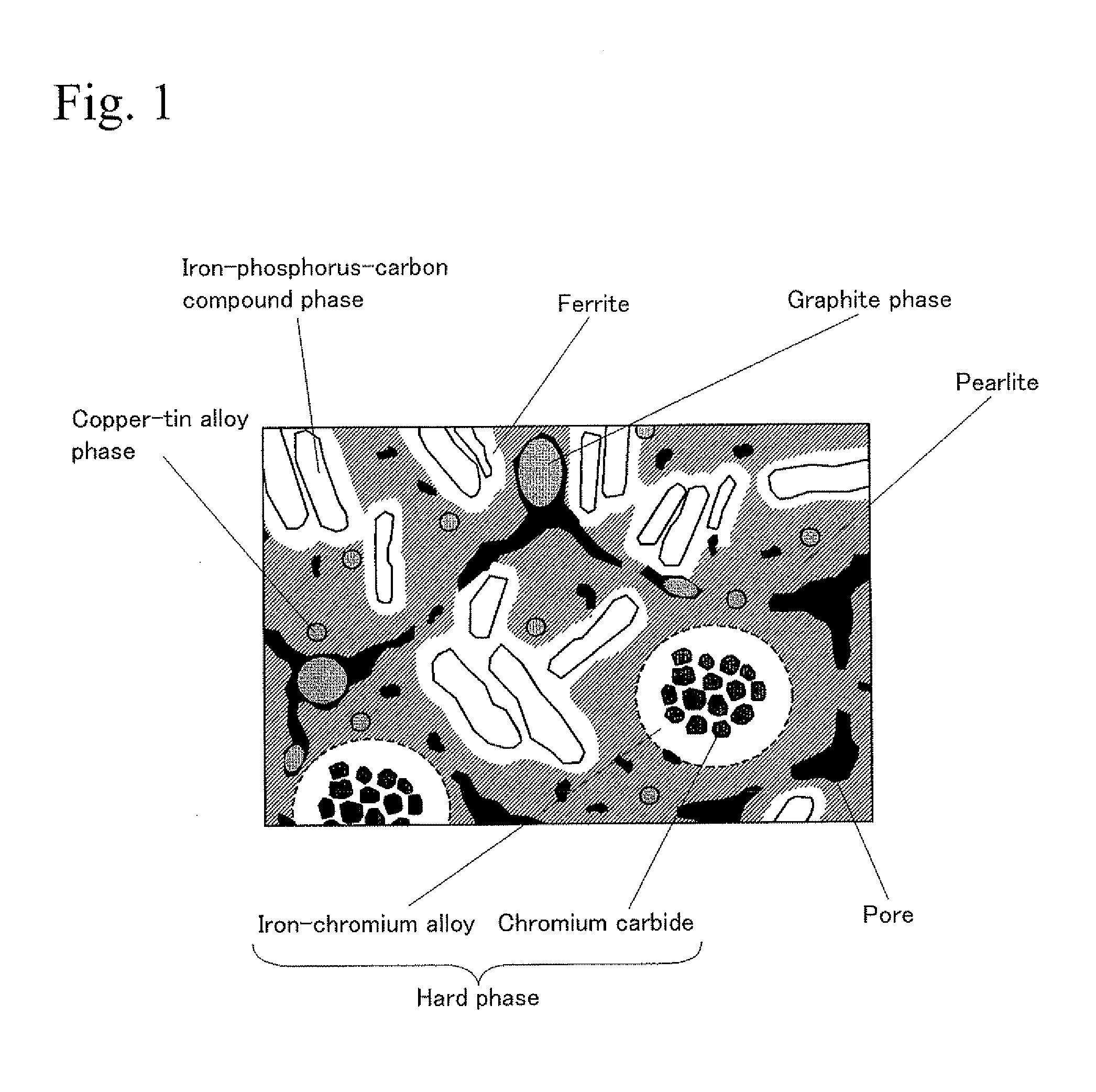
[0013]In the sintered valve guide of the present invention, the Fe—P—C ternary eutectic phase (hereinafter called “iron-phosphorus-carbon compound phase”) and also the hard phase are dispersed in the iron-based matrix, whereby the wear resistance is improved. Therefore, the sintered valve guide of the present invention is preferably used for valve guides used in sliding conditions that have recently become severe. Moreover, according to the production method for the sintered valve guide of the present invention, the sintered valve guide can be produced as easily as in a conventional manner.

Problems solved by technology

Moreover, in view of recent environmental issues, amounts of lubricant supplied to an interface between a valve guide and a valve stem have decreased.

Method used


Image

  • Sintered valve guide and production method therefor
  • Sintered valve guide and production method therefor

Examples


examples

[0064]The present invention will be described in further detail with reference to practical examples hereinafter.

first example

[0065]The effects of the amount of the hard phase forming powder on characteristics of a sintered valve guide were investigated. An atomized iron powder as an iron powder, an iron-phosphorus alloy powder consisting of 20 mass % of P and the balance of Fe and inevitable impurities, and a hard phase forming powder consisting of 12 mass % of Cr, 1.5 mass % of C, and the balance of Fe and inevitable impurities were prepared. In addition, an electrolytic copper powder as a copper powder, a copper-tin alloy powder consisting of 10 mass % of Sn and the balance of Cu and inevitable impurities, and a graphite powder were prepared. These powders were mixed at the mixing ratios shown in Table 1, whereby raw powders were obtained. The raw powders were compacted at a compacting pressure of 6.0 ton / cm2 and were formed into green compacts with a tube shape. Some of the green compacts had an outer diameter of 11 mm, an inner diameter of 6 mm, and a length of 40 mm (for a wear test and a machinabili...

second example

[0076]The effects of the amounts of Cr and C in the hard phase forming powder on the characteristics of a sintered valve guide were investigated. The iron powder, the iron-phosphorus alloy powder, the copper powder, the copper-tin alloy powder, and the graphite powder, all of which were used in the First Example, were prepared. In addition, hard phase forming powders including different amounts of Cr and C were prepared. These powders were mixed at mixing ratios shown in Table 3, and raw powders were obtained. The raw powders were formed into sintered alloy samples in the same manner as those in the First Example, whereby sintered alloy samples of samples Nos. 09 to 22 were obtained. The wear test and the compressive strength test were performed on these sintered alloy samples under the same conditions as those in the First Example, and the wear amounts and the compressive strengths were measured. The overall compositions and the test results of these samples are shown in Table 4. I...


PUM

PropertyMeasurementUnit
Temperatureaaaaaaaaaa
Fractionaaaaaaaaaa
Fractionaaaaaaaaaa

Abstract

A sintered valve guide exhibits a metallic structure having a mixed structure and a hard phase in which hard particles are dispersed in an alloy matrix. The mixed structure consists of pearlite, an Fe—P—C ternary eutectic phase, a ferrite phase, a copper phase, and pores, and the mixed structure consists of, by mass %, 0.075 to 0.525% of P, 3.0 to 10.0% of Cu, 1.0 to 3.0% of C, and the balance of Fe and inevitable impurities. The hard phase is dispersed at 2 to 15 mass % in the mixed structure.

Description

BACKGROUND OF THE INVENTION[0001]1. Technical Field[0002]The present invention relates to a sintered valve guide that may be used in an internal combustion engine, and also relates to a production method for the sintered valve guide. Specifically, the present invention relates to a technique for further improving wear resistance of the sintered valve guide.[0003]2. Background Art[0004]A valve guide used in an internal combustion engine is a tubular component having an inner circumferential surface for guiding valve stems of an intake valve and an exhaust valve. The intake valve may be driven so as to take fuel gas into a combustion chamber of the internal combustion engine, and the exhaust valve may be driven so as to exhaust combustion gas from the combustion chamber. Therefore, the valve guide is required to have wear resistance and is also required to maintain smooth sliding conditions so as not to cause to wear the valve stems for long periods. Valve guides made of a cast iron a...

Claims


Application Information

Patent Timeline
IPC IPC(8): B22F3/12B22F1/00
CPCC22C1/1084C22C32/0047C22C33/0228F01L2101/00C22C33/0257F01L1/16F01L3/08C22C33/0242F01L2301/00C22C33/0264C22C33/0278C22C33/0285C22C38/008C22C38/16
Inventor FUJITSUKA, HIROKIKAWATA, HIDEAKI
Owner RESONAC CORP
Learn More