Self-healing insulation for magnet wire

a self-healing and magnet wire technology, applied in the direction of insulated conductors, cables, magnetic bodies, etc., can solve the problems of small cracks or other defects, promote damage to the insulating layer, and affect the electrical resistance of the insulating layer, so as to achieve the effect of preventing electrical shorting and suitable electrical resistan

Active Publication Date: 2011-06-23
GM GLOBAL TECH OPERATIONS LLC
View PDF4 Cites 15 Cited by
  • Summary
  • Abstract
  • Description
  • Claims
  • Application Information

AI Technical Summary

Benefits of technology

[0012]Magnet wire electrical conductors may be formed in different cross-sectional and length-wise shapes for use in electrical devices such as coils, solenoids, transformers, generators and motors. The conductors are often extruded to obtain a desired cross-section. Long coils or shorted shapes may be fowled. At some stage in their manufacture the conductors are coated with a thin liquid layer of electrical insulating composition (often polymeric) which is then dried or cured to obtain a suitable level of electrical resistance to prevent electrical shorting in an assembled electrical device. However, it is often necessary to wind the magnet wire on a rotor or stator or otherwise shape it for placement in a magnet wire-supporting body assembly. Such shaping of the magnet wire may stress the hardened insulation layer and produce small cracks or other defects that impair its electrical resistance. This invention provides self-healing coatings for magnet wires that can repair such defects in the electrical insulation.

Problems solved by technology

However, it is often necessary to wind the magnet wire on a rotor or stator or otherwise shape it for placement in a magnet wire-supporting body assembly.
Such shaping of the magnet wire may stress the hardened insulation layer and produce small cracks or other defects that impair its electrical resistance.
However the microcapsules are composed to rupture under conditions which promote damage to the insulating layer.
Thus any mechanical loading experienced by the insulation and capable of damage to the insulation will be transmitted to the capsule, causing it to rupture and release its contents.

Method used


Image

  • Self-healing insulation for magnet wire
  • Self-healing insulation for magnet wire
  • Self-healing insulation for magnet wire

Examples


Embodiment Construction

[0026]Electric motors with ratings of 80 HP to 170 HP are becoming increasingly important as drive motors in automobiles, either individually or in combination with an internal combustion engine.

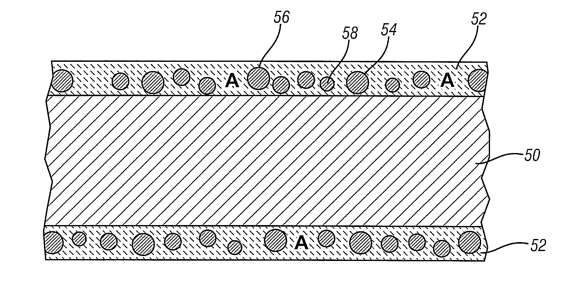
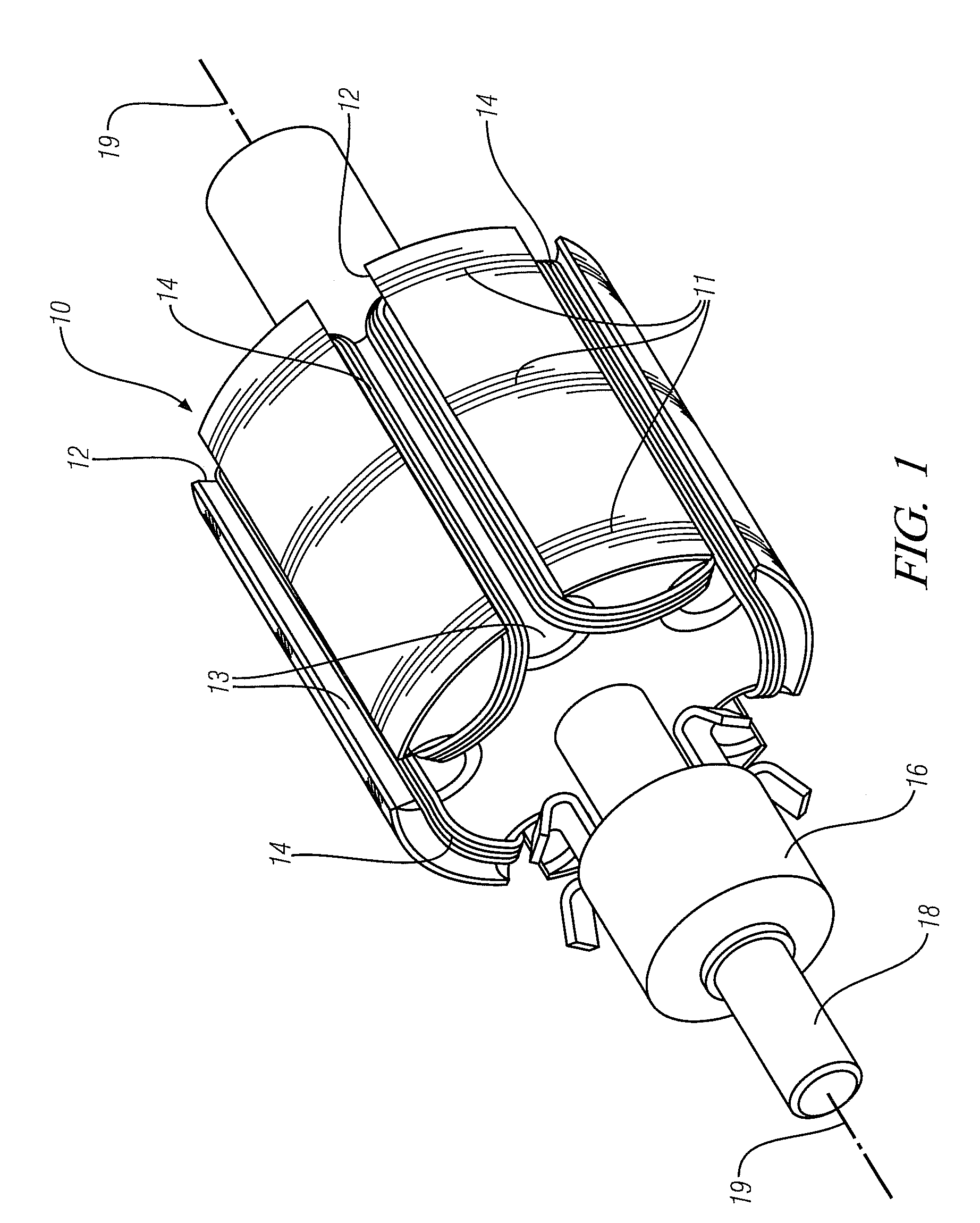
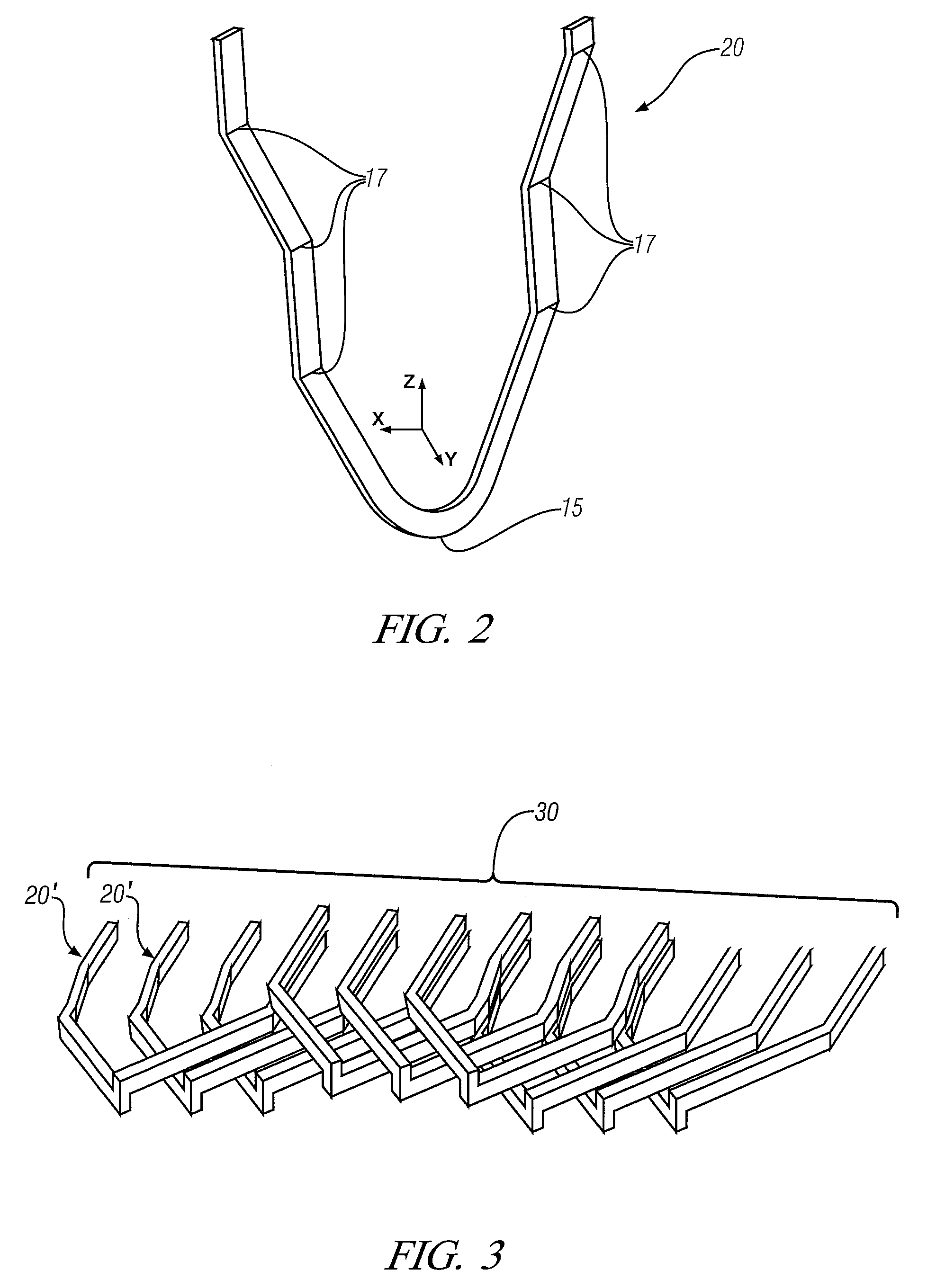
[0027]Such electric motors generally employ low resistance conductors, typically in the form of wire of round, square or rectangular cross-section positioned in narrow channels provided in structures fabricated from low reluctance materials. Copper conductors are preferred but aluminum may also be employed. These copper conductors, coated with a thin layer of insulating material and more commonly referred to as magnet wire, are provided to a motor manufacturer in extended lengths and generally packaged as a compact coil wrapped around a cylindrical spool or bobbin. The wire is then unwrapped from the spool or bobbin before undergoing additional processing to fabricate forms suitable for electric motor application and is then installed in either the rotor or the stator, or both, of an electri...


PUM

PropertyMeasurementUnit
Temperatureaaaaaaaaaa
Percent by volumeaaaaaaaaaa
Temperatureaaaaaaaaaa

Abstract

A process for remediating the insulating properties of magnet wire insulation is described. Magnet wire, used in electric motors and other electrical devices, comprises an electrically-conductive core covered by a thin insulating layer. The insulating layer may be damaged or compromised during manufacture or service. A process for incorporating polymerizable materials, sequestered in microcapsules, within the insulating layer is described. When the insulating layer is subjected to conditions sufficient to compromise its insulating character, the microcapsules fracture and release their contents which then polymerize and re-establish the insulating properties of the layer.

Description

TECHNICAL FIELD[0001]This invention pertains to the development of insulating coverings for electrical conductors, particularly for copper conductors used in electrical motors. The insulating coverings incorporate encapsulated chemical species capable of regenerating an electrically-insulating coating on the wire should the initially-applied coating be nicked, ruptured, or otherwise undergo damage which reduces its insulating capability.BACKGROUND OF THE INVENTION[0002]Electric motors operate through the interaction of opposing magnetic fields associated with a stationary element, a stator, most frequently generally resembling a hollow cylinder and a generally cylindrical rotating element, a rotor, whose axis lies on the axis of the stator. Either or both of these magnetic fields may be electrically generated by the passage of current through an electrical conductor.[0003]More generally, multiple conductors are used, with the conductors configured to produce additive interaction of ...

Claims


Application Information

Patent Timeline
IPC IPC(8): H01B7/00H01B19/00H01B3/30H02K15/00
CPCH02K3/30Y10T29/49227Y10T29/49009Y10T29/5187Y10T29/4902
Inventor PERRY, THOMAS A.SACHDEV, ANIL K.RODGERS, WILLIAM R.
Owner GM GLOBAL TECH OPERATIONS LLC
Why Eureka
Try Eureka