
Device and methods for discharging pretreated biomass from higher to lower pressure regions

a technology of biomass and lower pressure, which is applied in the direction of liquid transfer devices, liquid/fluent solid measurement, combustible gas production, etc., can solve the problems that the previous solutions to the “discharge” problem have generally not been suitable for continuous biomass processing, and achieve the effect of reducing heat and steam loss and strong turbulence in the lower

Active Publication Date: 2011-06-23
INBICON AS
View PDF30 Cites 9 Cited by
  • Summary
  • Abstract
  • Description
  • Claims
  • Application Information

AI Technical Summary

Benefits of technology

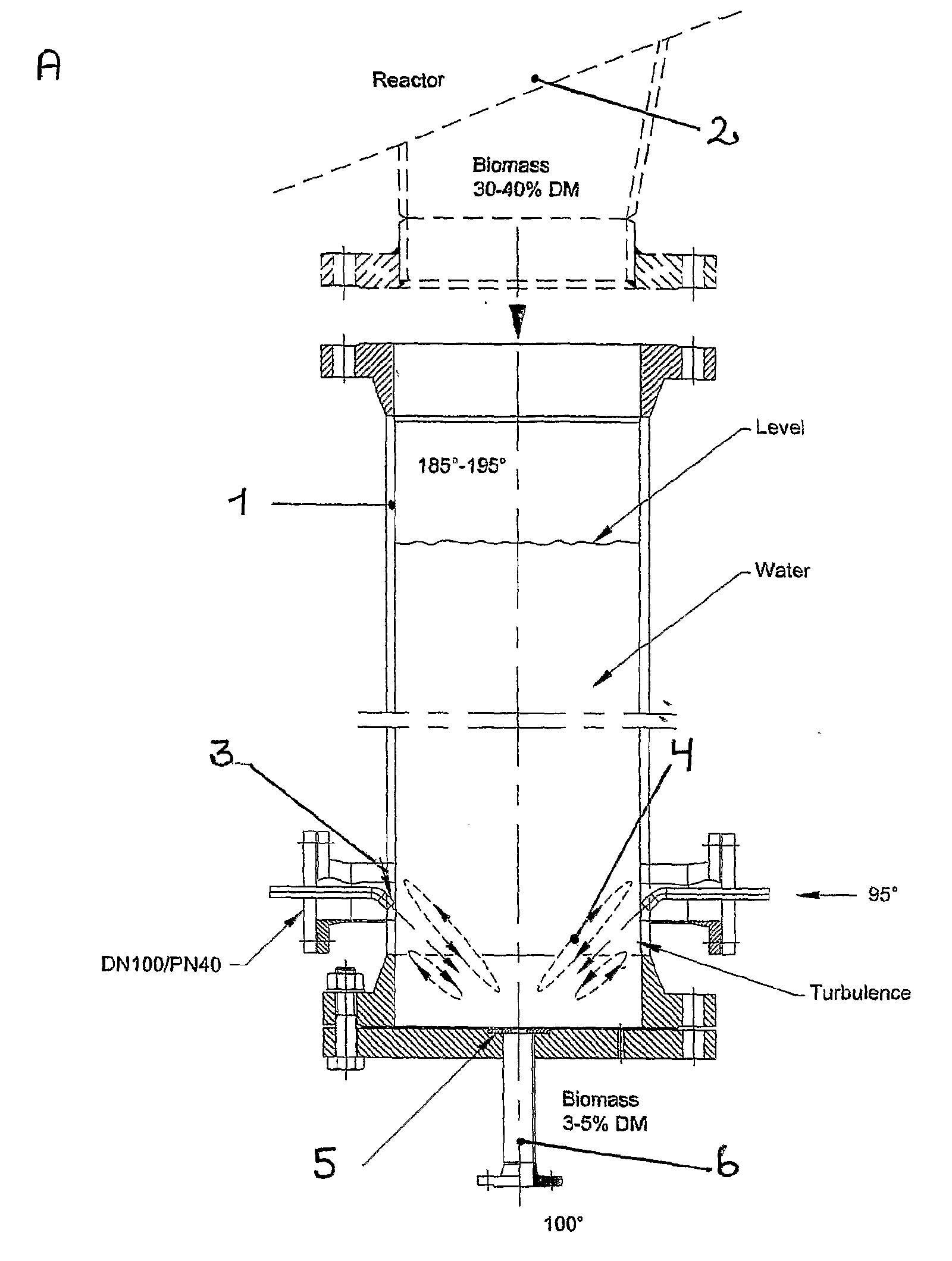
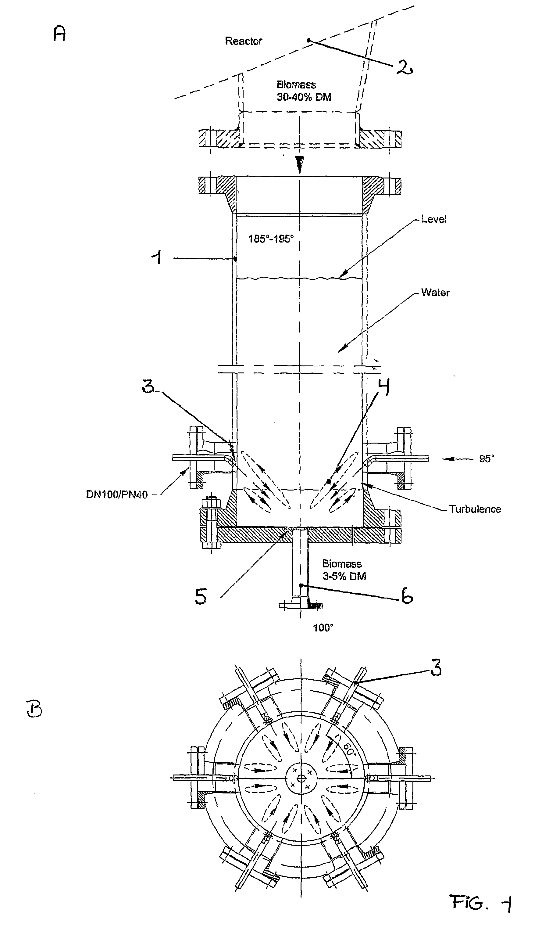
[0006]Provided are devices and methods for discharging pretreated biomass from higher to lower pressure regions. Pretreated, hot biomass is added under high pressure at the top of the discharge vessel, which is partially filled with water or aqueous solution. The vessel comprises a plurality of water jets situated on its sides through which water or aqueous solution is injected in order to establish a strong turbulence in the lower part of the vessel. This turbulence, preferably a vortex turbulence or “hydrocyclone,” blends biomass and water and disintegrates any clumped material prior to its ejection at high speed as a slurry through an orifice or valve at the bottom of the vessel. A stable temperature stratification is established within the discharge vessel, whereby hot water remains at the top of the vessel, reducing heat and steam loss from the pretreatment reactor.

Problems solved by technology

Discharge of pretreated biomasses from high pressure regions to subsequent processing at lower or atmospheric pressure presents a technical problem that has previously been solved by two general approaches.
Previous solutions to the “discharge” problem have generally not been suitable for continuous biomass processing.

Method used


Image

  • Device and methods for discharging pretreated biomass from higher to lower pressure regions
  • Device and methods for discharging pretreated biomass from higher to lower pressure regions
  • Device and methods for discharging pretreated biomass from higher to lower pressure regions

Examples


example

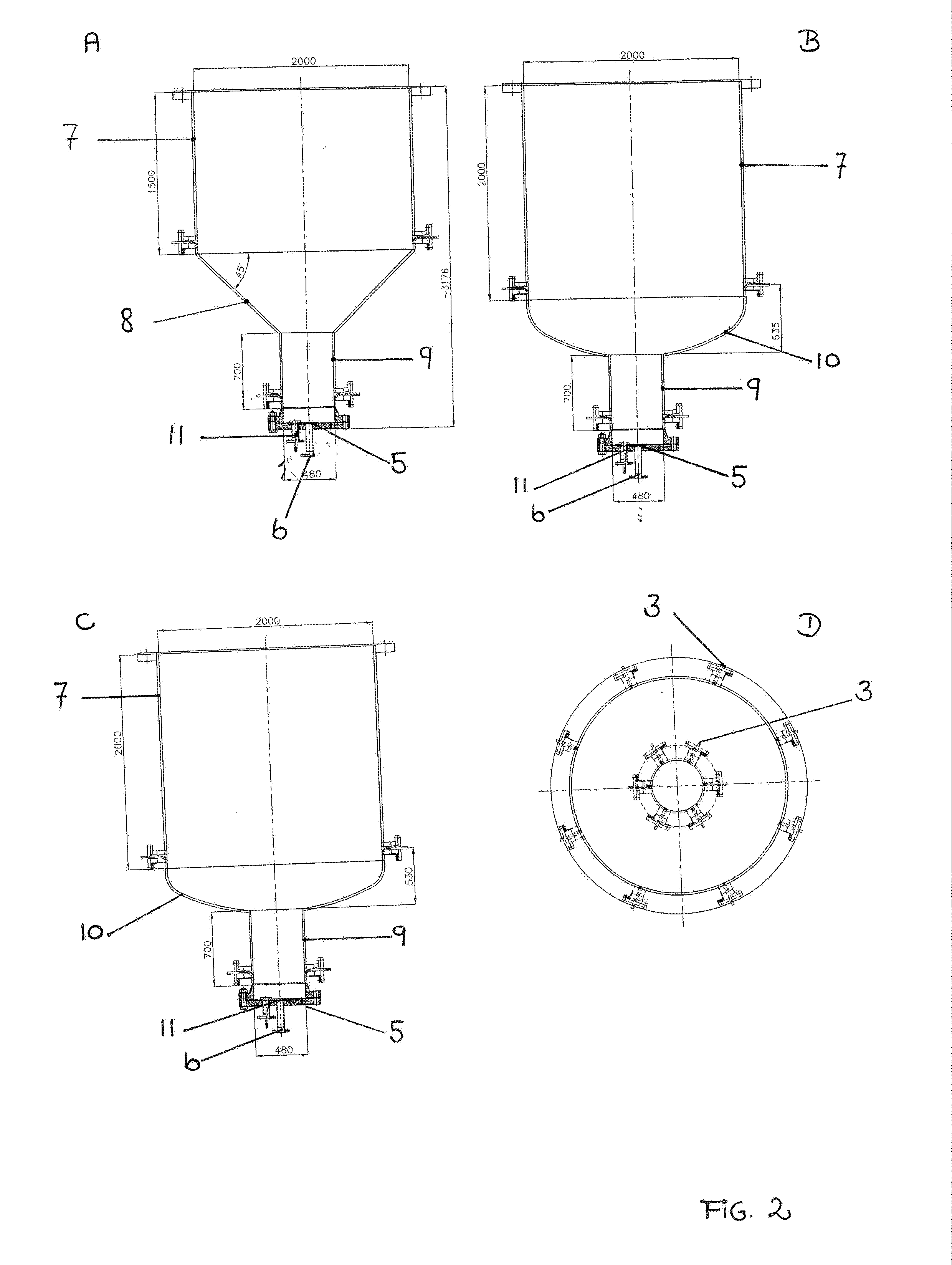
[0038]A device according to the invention was tested at INBICON's pilot facility in Skærbæk, Denmark. The device comprised a substantially cylindrical discharge vessel about 2.0 meters in height and 0.5 m in diameter. The vessel had a volume of 390 l and was mounted on a pressurized biomass pretreatment reactor having capacity for processing 1000 kg of wheat straw per hour at temperatures up to 220° C. The device was tested using three different kinds of biomass feedstock—wheat straw, corn stover, and maize silage. In all cases, biomass was cut to sizes between 1 and 10 cm longest dimension and steam treated at between 185 and 195° C. In all cases, the device was operated with a water level of about 290 l in the discharge vessel. The water level in the vessel was controlled by a valve that acted to open and close the discharge outlet and that was regulated by a water level sensor set to turn on at 1.3 meters level and off at 1.5 meters level. The discharge outlet had a diameter of b...


PUM

PropertyMeasurementUnit
Temperatureaaaaaaaaaa
Angleaaaaaaaaaa
Angleaaaaaaaaaa

Abstract

Provided are devices and methods for discharging pretreated biomass from a pressurized reactor. Pretreated, hot biomass is added under high pressure at the top of a discharge vessel, which is partially filled with water or aqueous solution. The vessel comprises water jets situated on its sides through which water or aqueous solution is injected in order to establish a strong turbulence in the lower part of the vessel. This turbulence, preferably a vortex turbulence or “hydrocyclone,” blends biomass and water and disintegrates any clumped material prior to its ejection at high speed as a slurry through an orifice or valve at the bottom of the vessel. A stable temperature stratification is established within the discharge vessel, whereby hot water remains at the top of the vessel, reducing heat and steam loss from the pretreatment reactor.

Description

FIELD OF THE INVENTION[0001]The invention relates to means and methods for discharging biomass that have been subject to pressurized treatments into lower or atmospheric pressure regions.BACKGROUND[0002]An intense interest has arisen in fermentation and gasification of carbohydrate-rich biomass to provide alternatives to petrochemical sources for fuels, livestock feeds and for organic chemical precursors. Lignocellulosic biomasses including industrial and agricultural wastes have proved particularly interesting as carbohydrate sources. For lignocellulosic biomasses, pretreatment is generally required in order to separate lignin and hemicellulose from cellulose fibers and thereby increase catalytically effective access of hydrolytic enzymes. A variety of pretreatment processes have been reported, many of which rely on high temperature treatments at high pressures. For review, see ref. 1 and 2.[0003]Discharge of pretreated biomasses from high pressure regions to subsequent processing ...

Claims


Application Information

Patent Timeline
IPC IPC(8): B67D7/08
CPCB01J4/002B01J2204/005C10J3/506C10J2200/15Y02E50/30C10J2300/0916C10L1/326C10L5/44Y02E50/10C10J2300/0903
Inventor VIBE-PEDERSEN, JAKOBIVERSEN, FRANK KROGH
Owner INBICON AS
Learn More