Apparatus and method for rapid charging using shared power electronics

a technology of power electronics and apparatus, applied in the direction of electric energy management, safety/protection circuits, and arrangements for several simultaneous batteries, can solve the problems of limited current available for recharging the on-board electrical storage device using only the on-board battery charging circuitry of the vehicle, and add additional cost and weight to the vehicle, so as to achieve rapid charging

Active Publication Date: 2011-06-23
GENERAL ELECTRIC CO
View PDF20 Cites 68 Cited by
  • Summary
  • Abstract
  • Description
  • Claims
  • Application Information

AI Technical Summary

Benefits of technology

[0007]According to one aspect of the invention, an apparatus comprises a power electronic energy conversion system comprising a first energy storage device configured to store DC energy and a first voltage converter configured to convert a stored voltage from the first energy storage device into a first voltage configured to drive an electromechanical device. The first voltage converter is also configured to convert a second voltage from a remote power supply into a first charging voltage configured to charge the first energy storage device. The

Problems solved by technology

These additional dedicated components add extra cost and weight to the vehicle.
In addition, the total current available for recharging the on-board electrical storage device using only the on-board battery charging circuitry of the vehicle is limited to the total current t

Method used


Image

  • Apparatus and method for rapid charging using shared power electronics
  • Apparatus and method for rapid charging using shared power electronics
  • Apparatus and method for rapid charging using shared power electronics

Examples


Embodiment Construction

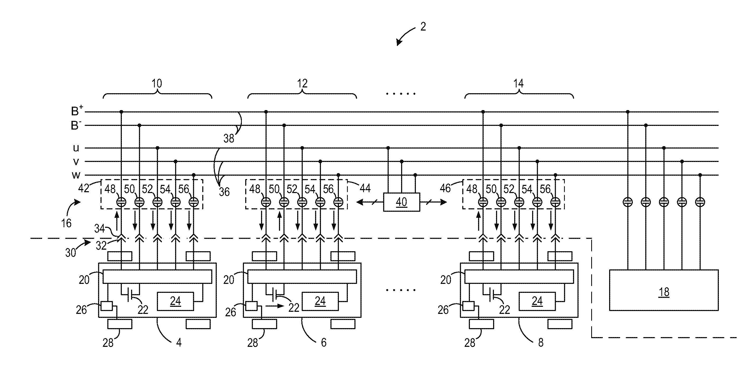
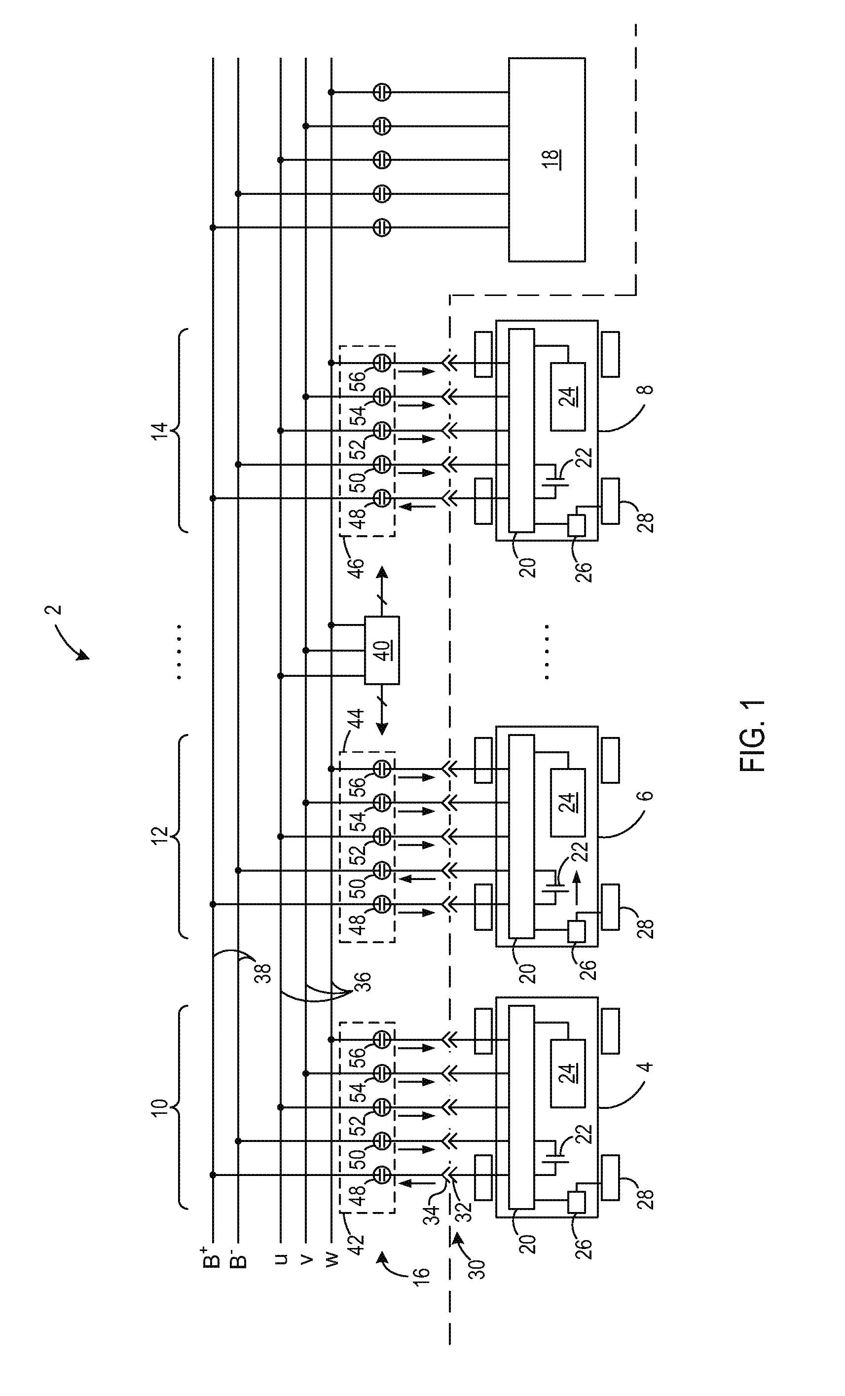
[0023]FIG. 1 is a schematic block diagram of the infrastructure of a charging system 2 according to an embodiment of the invention. Charging system 2 illustrates a plurality of vehicles 4, 6, 8 coupled to a respective charging bay or socket 10, 12, 14 of a charging station 16. Charging system 2 may include, in one embodiment, a non-vehicle charging unit 18 as described below with respect to FIGS. 7-9. According to embodiments of the invention, vehicles 4-8 and charging station 16 are configured to cooperate together to share power electronics among the vehicles 4-8 and optional off-board charging unit 18 to provide a charging current to one of the vehicles, such as vehicle 6, to augment and increase the charging current generated by the vehicle alone.

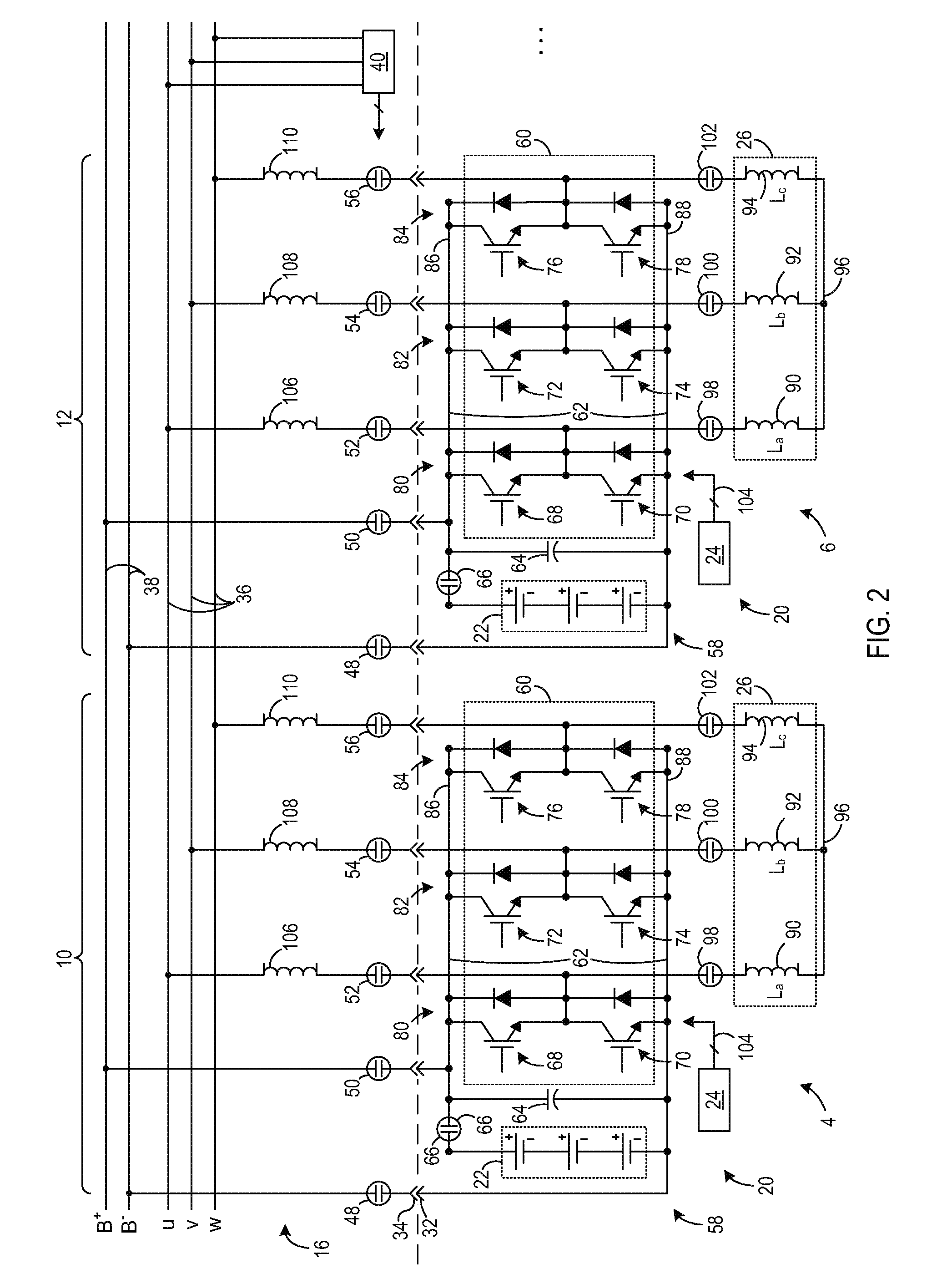
[0024]Each vehicle 4-8 includes a plurality of power electronics 20 coupled to a least one energy storage device 22. During operation of vehicle 4-8, a controller 24 causes a DC voltage from energy storage device 22 to be modified and d...


PUM


Abstract

An apparatus comprises a power electronic energy conversion system comprising a first energy storage device configured to store DC energy and a first voltage converter configured to convert a second voltage from a remote power supply into a first charging voltage configured to charge the first energy storage device. The apparatus also includes a first controller configured to control the first voltage converter to convert the second voltage into the first charging voltage and to provide the first charging voltage to the first energy storage device during a charging mode of operation and communicate with a second controller located remotely from the power electronic energy conversion system to cause a second charging voltage to be provided to the first energy storage device during the charging mode of operation to rapidly charge the first energy storage device.

Description

BACKGROUND OF THE INVENTION[0001]Embodiments of the invention relate generally to electric drive systems including hybrid and electric vehicles and, more particularly, to rapidly charging one electric drive system using shared power electronics of one or more additional electric drive systems.[0002]Hybrid electric vehicles may combine an internal combustion engine and an electric motor powered by an energy storage device, such as a traction battery, to propel the vehicle. Such a combination may increase overall fuel efficiency by enabling the combustion engine and the electric motor to each operate in respective ranges of increased efficiency. Electric motors, for example, may be efficient at accelerating from a standing start, while combustion engines may be efficient during sustained periods of constant engine operation, such as in highway driving. Having an electric motor to boost initial acceleration allows combustion engines in hybrid vehicles to be smaller and more fuel effici...

Claims


Application Information

Patent Timeline
IPC IPC(8): H02J7/04B60L50/30
CPCB60L7/12Y02T10/7066B60L9/22B60L9/28B60L11/005B60L11/16B60L11/1803B60L11/1805B60L11/1811B60L11/1816B60L11/185B60L11/1857B60L11/1868B60L11/1887B60L2200/36B60L2210/14B60L2210/30B60L2210/40B60L2240/72H02J7/0013H02J7/0027Y02T10/7291Y02T90/121Y02T90/127Y02T90/128Y02T90/14Y02T90/16Y02T90/163Y02T90/168Y02T90/34Y04S30/12Y02T10/7241Y02T10/7022Y02T10/7225B60L7/14B60L53/14B60L50/40B60L50/30B60L50/51B60L50/52B60L53/20B60L58/16B60L58/20B60L58/40Y10S903/903B60L53/11H02J2310/48H02J2207/20Y02T90/167Y02T10/7072Y02T10/70Y02T10/72Y02T90/12Y02T90/40H02J7/0029H02J7/0045
Inventor KING, ROBERT DEANSTEIGERWALD, ROBERT LOUIS
Owner GENERAL ELECTRIC CO
Why Eureka
Try Eureka