Printing system, printing method, image processing system, and image processing method

Active Publication Date: 2011-06-23
CANON KK
View PDF9 Cites 10 Cited by
  • Summary
  • Abstract
  • Description
  • Claims
  • Application Information

AI Technical Summary

Benefits of technology

[0010]In view of the foregoing issues, the present invention provides a printing system and an image processing system that can print patches with which high accuracy measurement can be performed in a short time even when a sensor measures the patches while relatively moving over a paper sheet.
[0012]According to the present invention, by generating patch image data having a patch length corresponding to the optical density of the patch, advantages are obtained in that SN for a high-optical-density patch is improved and a patch chart can be measured in a short time.

Problems solved by technology

However, for a high-optical-density patch, that is a dark patch, a signal to be received becomes small and the relative proportion of the noise components becomes large, and thus the SN ratio deteriorates.
In particular, in an inexpensive sensor, since the SN ratio, which is the ratio of a signal value to noise, is small and thus the relative ratio of noise to a signal value becomes large, noise has a large impact on the signal value, thereby reducing the accuracy of measurement.
In the case of increasing the light quantity, problems such as a thermal problem and a change in the spectral characteristics of the light sources may occur and, in addition, a bright patch may cause signal saturation.
Also in the case of increasing the amplification factor, a bright patch is likely to cause signal saturation and, in addition, the noise itself may be amplified.
Further, a colorimetric sensor, in general, performs color measurement after calibrating white balance, however, since the color measurement needs to be performed under the same conditions as those used when the calibration is performed in order to prevent the above-mentioned error, changing the light quantity or the amplification factor for each patch during the color measurement may increase the colorimetric error.
Meanwhile, since the influence of the noise is large when the reflected signal values are small, as in FIG. 1B, the measurement time t1 is not sufficient to ensure the accuracy.
However, in order to converge the noise components to near zero in the averaging procedure, it is necessary to take a longer measurement time for darker patches, thereby taking a longer time to measure the whole patch chart.
However, if the length of each patch is adjusted to the length with which the darkest patch can be measured stably, there is a problem in that the total measurement time for measuring all the patches becomes longer.

Method used


Image

  • Printing system, printing method, image processing system, and image processing method
  • Printing system, printing method, image processing system, and image processing method
  • Printing system, printing method, image processing system, and image processing method

Examples


first embodiment

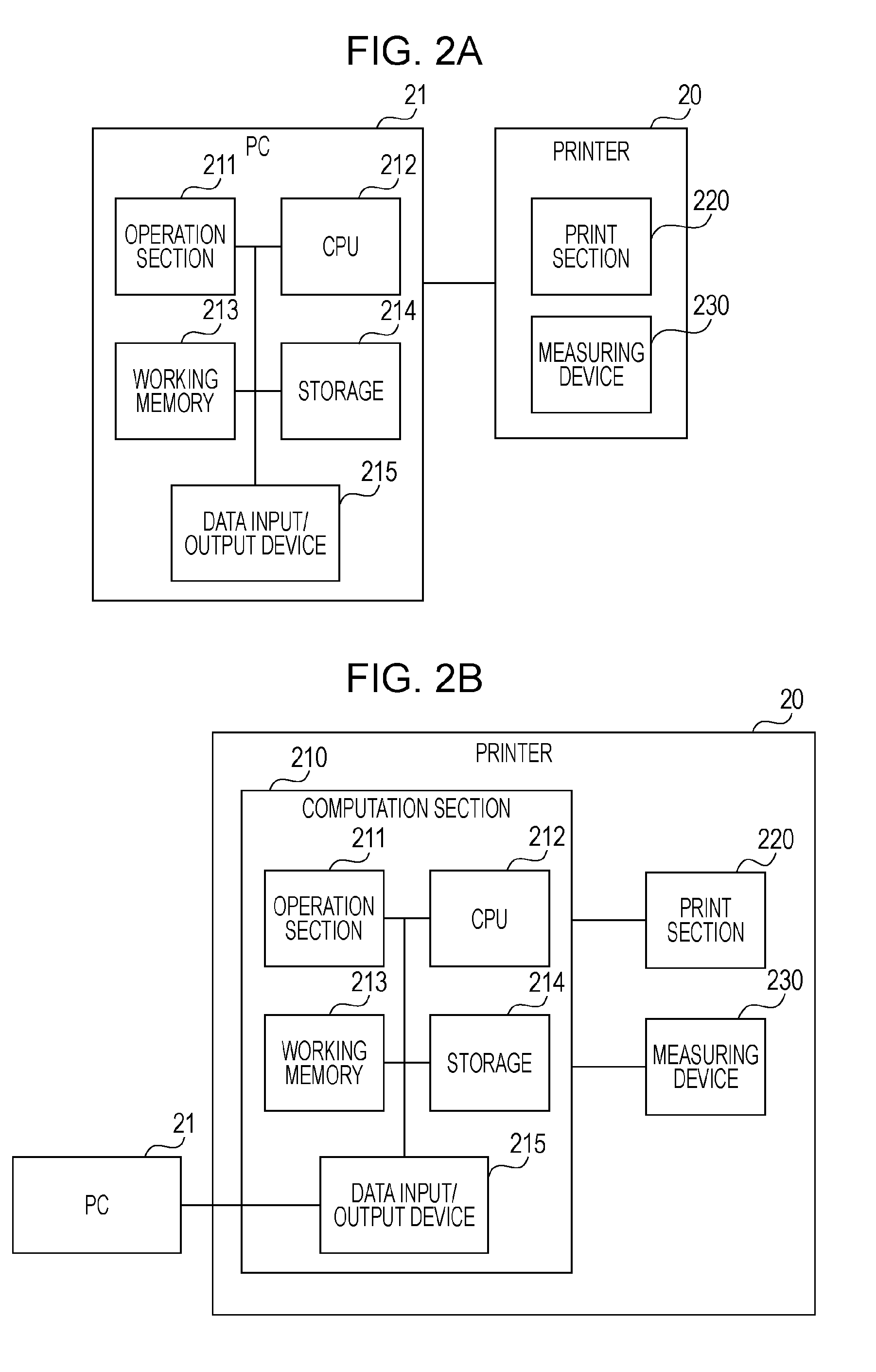
[0026]FIG. 2A shows a first configuration of an image processing system in an embodiment of the present invention.

[0027]In this embodiment, an ink-jet printer is used as a typical example. A printer 20 is connected to a personal computer (hereinafter simply referred to as a “PC”) 21 as an information processing apparatus and is constituted by a print section 220 for output and a measuring device 230 for measurement. The measuring device receives reflected light of irradiated light by using a sensor embedded in the measuring device and measures the reflectance factor by using the intensity of the light reflected from a target document. As a measuring device, a colorimetric device that uses spectral reflectance factors may be used. In this embodiment, the measuring device 230 is mounted on a movable carriage portion of the print section 220, as shown in FIG. 3, but may be attached to a paper ejection port or connected to an external portion of the printer. However, a measuring method ...

second embodiment

[0051]In step S602 of First Embodiment, the patch length is determined by color data of the patch by using the equations. Meanwhile, a lookup table (hereinafter referred to as an LUT) for converting a color value of a patch to a patch length may be stored in advance to determine the patch length by referring thereto. A method for creating an LUT will be explained below.

[0052]First, patch lengths are calculated by using the equations in step S602 for 9×9×9=729 input RGB values in which each of the R, G and B values is varied in 9 steps. Then, an LUT is created by using a tetrahedral interpolation technique, which is an existing commonly-used technique. The LUT created in this way is stored in advance in the storage 214. Then, the LUT, which is used to convert an RGB value to a patch length, is referred to when the patch length is determined in step S602.

[0053]Alternatively, an LUT for converting a color value of a patch to a patch length may be stored for each paper type. This is bec...

third embodiment

[0054]The LUT in Second Embodiment is created by determining the patch length by the equations by using the color value of a patch to generate patch image data. However, an LUT may be created on the basis of the color density or the spectral reflectance factor measured for each patch printed on paper. A method of creating the LUT by measuring the spectral reflectance factor will be explained below.

[0055]First, 9×9×9=729 patches, in which each of the R, G and B values is varied in 9 steps, are printed on a paper sheet on which the printer can print. Then, the spectral reflectance factor is measured for each patch by a colorimetric device. For the colorimetric device, it is advisable to use the same colorimetric device as that embedded in the printer. After the spectral reflectance factor is measured, the patch length is determined by using the measured spectral reflectance factor. FIG. 10 shows the spectral reflectance factors of the patches when patches having different input RGB va...


PUM


Abstract

According to the present invention, patch data is printed in such a manner that the length of a low-optical-density patch is small and the length of a high-optical-density patch is large. In addition, the measurement is performed by a sensor that measures at a constant scanning speed. Therefore, SN of a dark patch having a high optical density is improved, and a patch chart can be measured in a short time.

Description

BACKGROUND OF THE INVENTION[0001]1. Field of the Invention[0002]The present invention relates to a printing system, a printing method, an image processing system, and an image processing method for printing a patch that is measured by a sensor in order to obtain a measurement value.[0003]2. Description of the Related Art[0004]In recent years, many image output apparatuses, such as large ink-jet printers, equipped with a colorimetric device are in the marketplace. Such a colorimetric device is used for color calibration for correcting the print color density of a printer and stabilizing colors or to create an ICC profile. Colorimetric devices are mounted in various ways such as mounted on a carriage portion of the print head or provided in such a manner that a colorimetric device unit is attached and fixed to the paper ejection portion. Measurement methods of the colorimetric devices include contact and non-contact methods. In a contact method, measurement is performed while a colori...

Claims


Application Information

Patent Timeline
IPC IPC(8): H04N1/60
CPCH04N1/00002H04N1/00015H04N1/00023H04N1/00031H04N1/00045H04N2201/0006H04N1/00058H04N1/00063H04N1/00087H04N1/0009H04N1/6033H04N1/00053
Inventor OMAGARI, YUKIURATANI, MITSURUISHIDA, YUKIABE, SEIJIOBAYASHI, MASAAKI
Owner CANON KK
Why Eureka
Try Eureka