Radio antenna assembly and apparatus for controlling transmission and reception of RF signals

a technology of radio antennas and antenna assemblies, applied in the direction of antennas, post-communication radio transmission, transmission, etc., can solve the problems of device remote detonation, ineffective jamming signal, and receiver receiving less than desired signal strength, so as to improve the signal-to-noise ratio of communication links

Active Publication Date: 2011-06-23
ALLEN VANGUARD
View PDF11 Cites 19 Cited by
  • Summary
  • Abstract
  • Description
  • Claims
  • Application Information

AI Technical Summary

Benefits of technology

[0004]The inventors have discovered that when transmitting at certain frequencies from a vehicle mounted antenna, the signal strength is significantly lower than expected in certain regions in close proximity to the vehicle, and that such regions of lower than expected signal strength occur particularly for higher frequencies and where the vehicle significantly shadows and scatters the signal. Thus, as the vehicle moves towards an object, such as a receiver, the signal strength fades significantly when the vehicle is in close proximity with the receiver resulting in the receiver receiving less than the desired signal strength. In some applications, the signal emitted by the antenna comprises a jamming signal and the receiver may be a receiver for a remote controlled explosive device, for example. Accordingly, fading of the jamming signal when the vehicle is in close proximity to the receiver may render the jamming signal ineffective, and enable the explosive device to be remotely detonated.
[0005]In view of the above, it would be desirable to provide an improved antenna assembly which is capable of producing adequate signal strength and coverage in close proximity to the vehicle or other support on which it is mounted.

Problems solved by technology

Thus, as the vehicle moves towards an object, such as a receiver, the signal strength fades significantly when the vehicle is in close proximity with the receiver resulting in the receiver receiving less than the desired signal strength.
Accordingly, fading of the jamming signal when the vehicle is in close proximity to the receiver may render the jamming signal ineffective, and enable the explosive device to be remotely detonated.

Method used


Image

  • Radio antenna assembly and apparatus for controlling transmission and reception of RF signals
  • Radio antenna assembly and apparatus for controlling transmission and reception of RF signals
  • Radio antenna assembly and apparatus for controlling transmission and reception of RF signals

Examples


Embodiment Construction

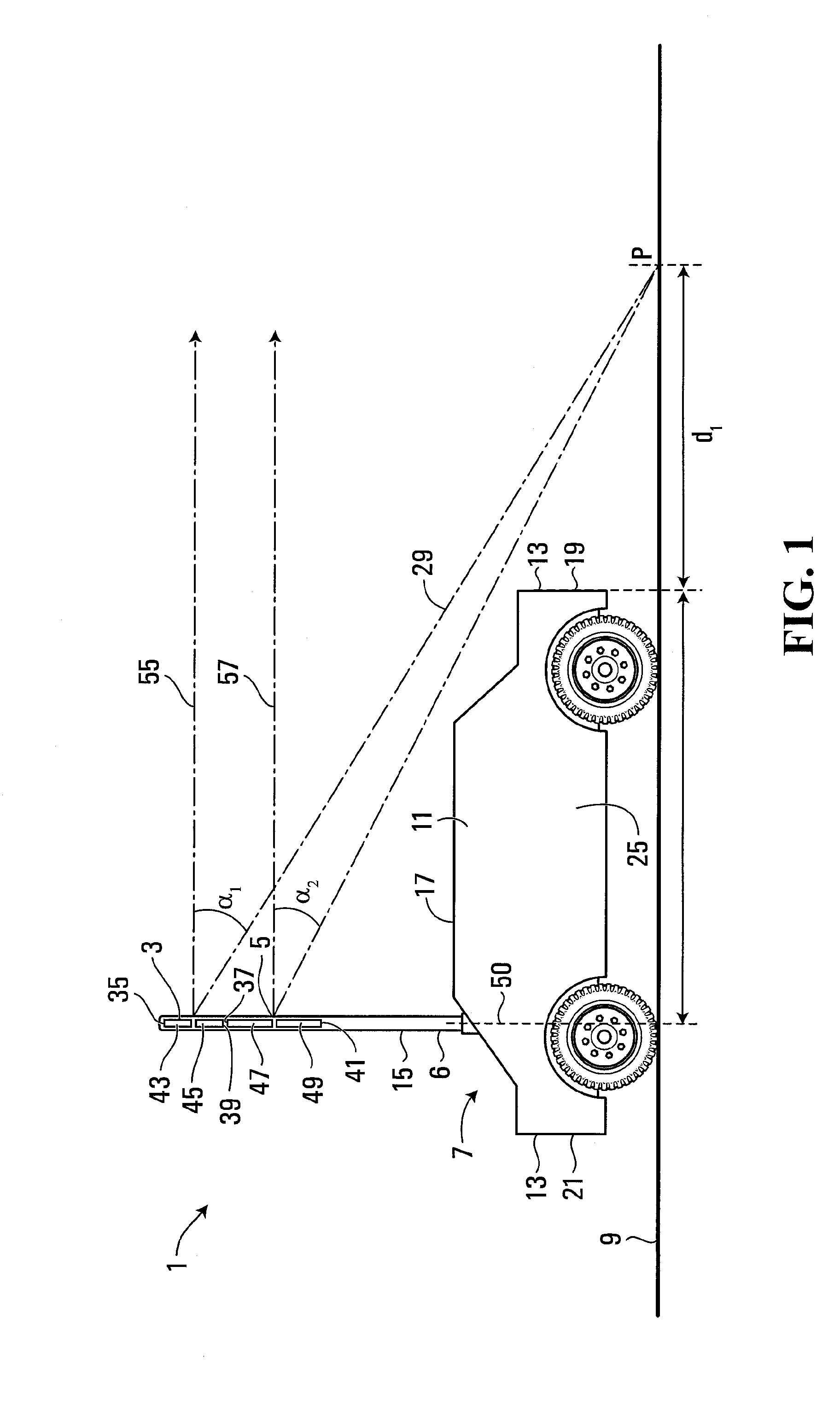
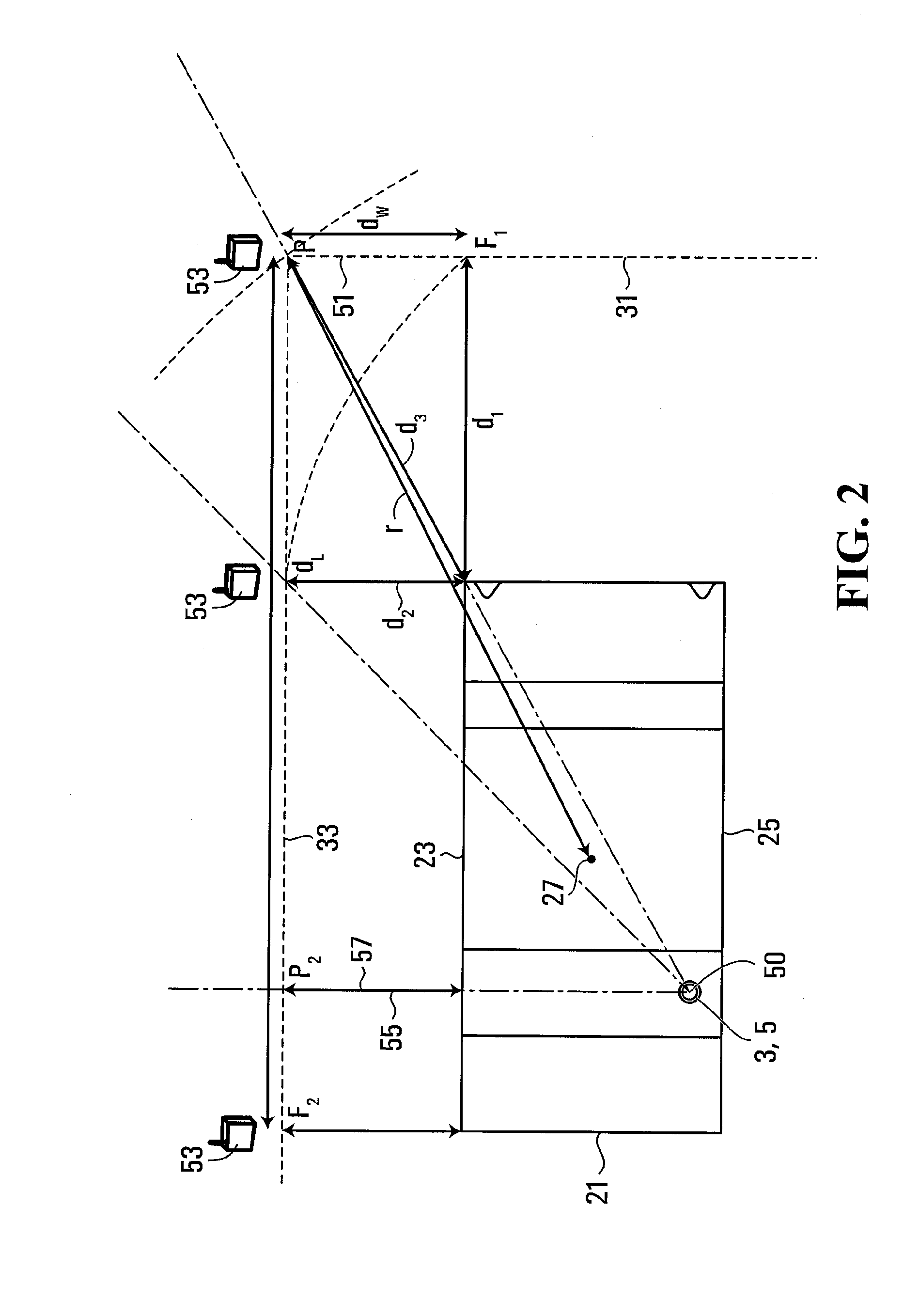
[0147]Referring to FIGS. 1 to 3, an antenna assembly 1 comprises a first antenna 3, a second antenna 5 and a support 6 for supporting the first and second antennas at an elevated position above a surface 9, when mounted on a predetermined support structure 7. In this embodiment, the support structure 7 comprises a mobile structure 11 having a peripheral edge 13. The antenna support comprises an upright member 15 upstanding from the mobile structure 11 for supporting the first and second antennas at a position above the top 17 of the mobile structure. Thus, together, the antenna support 6 and the support structure 7 support the antennas at an elevated position above the surface.

[0148]The mobile structure has opposed front and rear ends 19, 21 and opposed left and right sides 23, 25. In this embodiment, the first and second antennas are located at a position which is offset from the center 27 of the mobile support structure 11 towards the rear end 21 and towards the right side 25. In ...


PUM


Abstract

An apparatus includes an antenna for transmitting RF radiation and being structured to enable the distribution of RF energy emitted therefrom to be varied in the vertical plane. The apparatus comprises a generator for generating an RF signal and to pass the signal to the antenna, and a controller arranged to control the distribution of RF energy emitted from the antenna in the vertical plane in response to positional information about an object.

Description

FIELD OF THE INVENTION[0001]The present invention relates to radio antennas and antenna assemblies and in particular, but not limited to, antennas and antenna assemblies for vehicles and other mobile units.BACKGROUND OF THE INVENTION[0002]Vehicle mounted radio antennas are generally known for receiving radio broadcast signals and for two-way communication in mobile telephone applications. Vehicle mounted antenna are also known for voice communications in military applications.[0003]In static applications, a known antenna assembly comprises an antenna array comprising several vertically stacked dipole antennas each of which operates over the same frequency band. In transmission mode, each antenna is fed the same carrier frequency signal with the signal fed to the upper and lower antennas being phase shifted relative to middle antenna to increase the concentration of electromagnetic energy in the horizontal direction.SUMMARY OF THE INVENTION[0004]The inventors have discovered that whe...

Claims


Application Information

Patent Timeline
Patent Type & Authority Applications(United States)
IPC IPC(8): H04B7/24H04B1/04H01Q3/00
CPCH01Q1/1242H01Q1/325H01Q21/08H01Q9/18H01Q3/38
Inventor BONGFELDT, DAVID CHARLESLEWIS, NICLASYENSEN, TREVOR NOEL
Owner ALLEN VANGUARD
Why Eureka
Try Eureka