Method of Utilization of High Dielectric Constant (HDC) Materials for Reducing SAR and Enhancing SNR in MRI

a dielectric constant and high dielectric technology, applied in the field of radiofrequency electromagnetic field, can solve the problems of increasing the heating effect of tissue rf, using a higher static magnetic field strength from current 1 to 1.5 tesla to 3 to 7 tesla, and high cost, so as to enhance the image snr of the sample, enhance the performance of the rf coil, and reduce the transmission power

Active Publication Date: 2011-06-23
YANG QING X
View PDF3 Cites 20 Cited by
  • Summary
  • Abstract
  • Description
  • Claims
  • Application Information

AI Technical Summary

Benefits of technology

[0010]It is another object of this invention that HDC materials are incorporated into RF coils to reduce the transmission power for a given excitation flip-angle in a region of interest (ROI) inside the sample.
[0011]It is another object of this invention that HDC materials are incorporate into a or a set of RF receive coil to enhance the image SNR of the sample.
[0012]For certain applications in the art, it is desirable to have a strong and uniform B1 only in a part of the sample or a ROI in the sample. It is another object that HDC materials are incorporated into the coil or inside the sample to enhance an RF coil performance in term of an increase in SNR in a ROI near or around HDC materials in the sample and a decrease of input RF power, therefore, SAR in the sample during excitation of magnetization.
[0013]It is another object of this invention that HDC materials are used as a RF field trap to reduce radiation loss of high field MRI coils. In high field MRI (3 T, 4 T, 7 T and above), radiation loss becomes more significant as the corresponding RF field frequency increases.

Problems solved by technology

In particularly, this includes the use of higher static magnetic field strength from current 1 to 1.5 Tesla to 3 to 7 Tesla, which is extremely expensive.
Unfortunately, an increase in static magnetic field strength leads to a higher frequency of RF field, which, in turn, dramatically increases RF heating effect of the tissue (1) and creates RF field inhomogeneity artifacts (2-5).
These two problems pose serious challenges for high field MRI development in human imaging.

Method used


Image

  • Method of Utilization of High Dielectric Constant (HDC) Materials for Reducing SAR and Enhancing SNR in MRI
  • Method of Utilization of High Dielectric Constant (HDC) Materials for Reducing SAR and Enhancing SNR in MRI
  • Method of Utilization of High Dielectric Constant (HDC) Materials for Reducing SAR and Enhancing SNR in MRI

Examples


Embodiment Construction

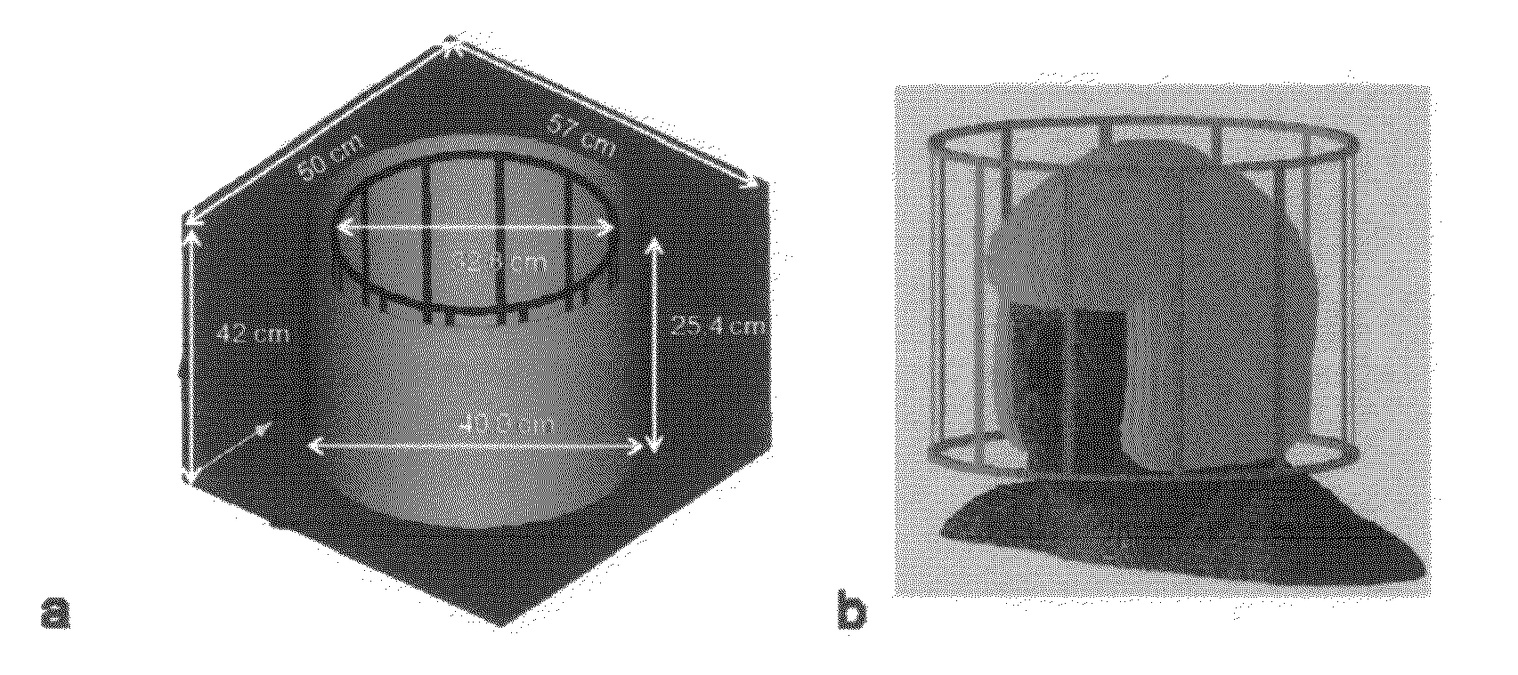
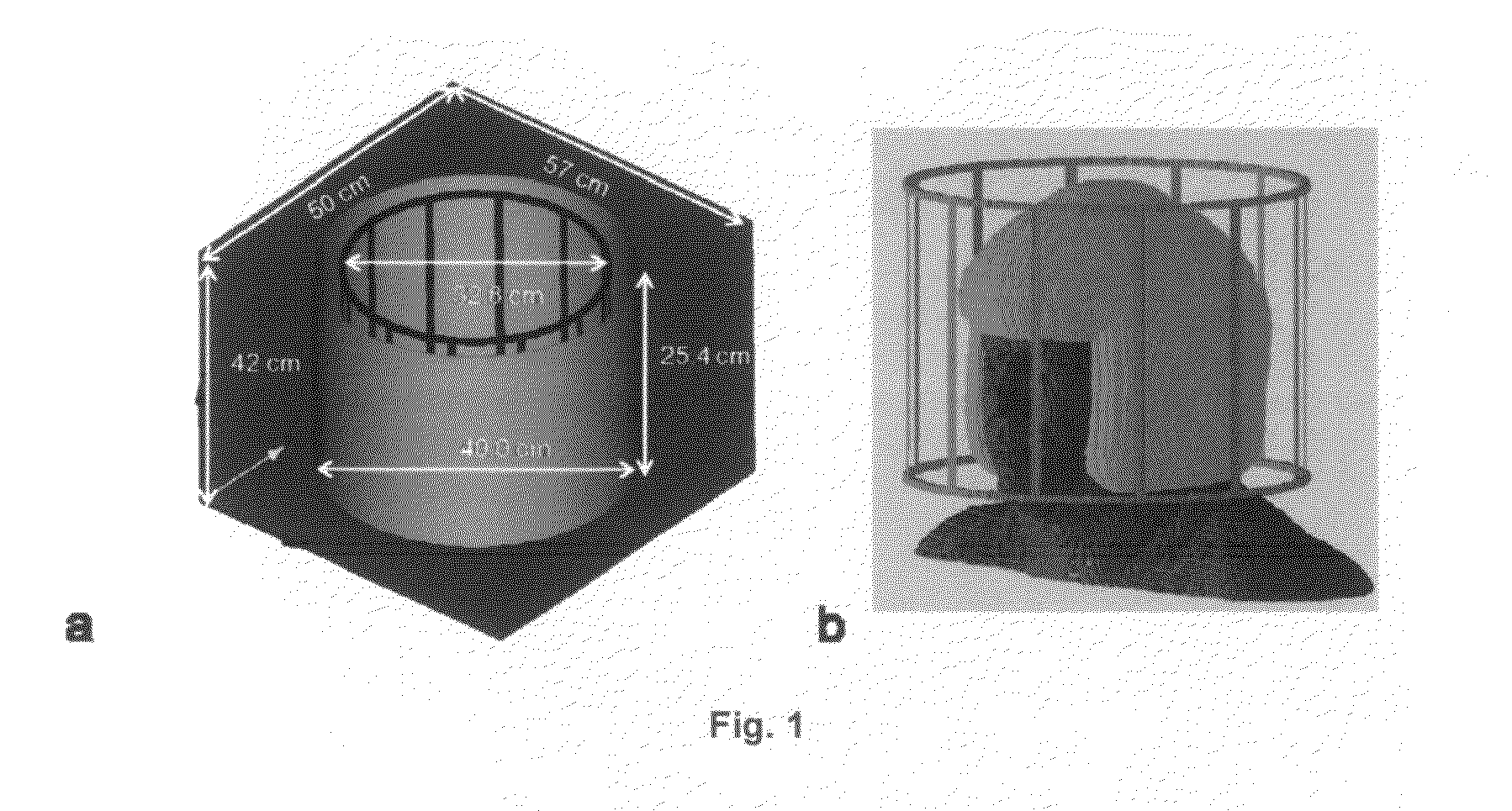
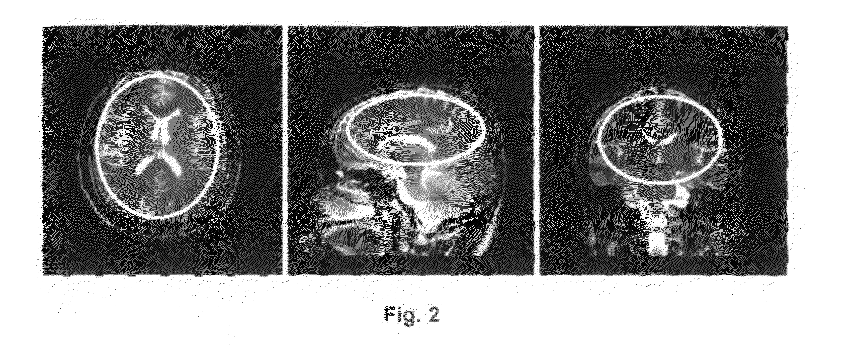
[0022]A preferred embodiment of the present invention will now be described in detail with reference to FIGS. 1-5. Those skilled in the art will appreciate that the description given herein with respect to those figures is for exemplary purposes only and is not intended in any way to limit the scope of the invention. All questions regarding the scope of the invention may be resolved by referring to the appended claims.

[0023]Theoretical Considerations

[0024]For conductive dielectric materials such as human brain tissues, the RF field inside the sample is perturbed by conductive current (Jc) and displacement current (Jd) according to Ampere's Law with Maxwell's correction,

∇×B=μJc+μJd=μσE+iμ∈r∈0 ωE  [1]

where B is magnetic flux density, E is electric field, ω is angular frequency, ∈r is relative electric permittivity (dielectric constant), ∈0 is the electric permittivity in vacuum, σ□ is electrical conductivity, m is magnetic permeability, and i=√{square root over (−1)} is the complex un...


PUM


Abstract

Layers or coats of materials with high dielectric constant or permittivity with very low conductivity are inserted in between radiofrequency (RF) coil or coil's conductive elements and the sample to enhance the signal to noise ratio (SNR), improve image contrast, and reduce the specific absorption rate (SAR) of magnetic resonance imaging or magnetic resonance spectroscopy instruments. The embodiments of the present invention can be used as an auxiliary device to the standard pre-constructed RF coils or incorporated with RF coil constructions for enhancing RF coil performances in both transmission and reception.

Description

STATEMENT AS TO RIGHTS TO INVENTIONS MADE UNDER FEDERALLY SPONSORED RESEARCH OR DEVELOPMENT[0001]This research was supported by Grant No R01 AG02771 from the NIH. The Government has certain rights in the invention.BACKGROUND OF THE INVENTION[0002]1. Field of the Invention[0003]This invention relates generally to the radiofrequency (RF) electromagnetic field, denoted as B1, used for magnetic resonance imaging (MRI) and magnetic resonance spectroscopy (MRS) spectroscopy instruments. Particularly, the invention relates to the use of materials with high dielectric constant (HDC) or permittivity with low electrical conductivity for RF field generation in the MRI or NMR instruments.[0004]2. Description of the Prior Art[0005]RF coils are used to produce RF magnetic field (B1) for excitation and detection of the magnetization signal from an object such as parts of human body during MRI and MRS data collections. The RF field can be generated by a coil or a set of coils. The RF field is trans...

Claims


Application Information

Patent Timeline
Patent Type & Authority Applications(United States)
IPC IPC(8): A61B5/055G01R33/48G01R33/28
CPCA61B5/055A61B5/415G01R33/565G01R33/288G01R33/5659A61B5/418
Inventor YANG, QING X.
Owner YANG QING X
Why Eureka
Try Eureka