Method for on board diagnostics and system for on board diagnostics

a diagnostic system and on-board diagnostic technology, applied in the direction of machines/engines, electrical control, instruments, etc., can solve the problems of high exhaust manifold pressure, turbo failing to create boost at low speed, and difficult to find the relationship between charge air pressure and these variables, so as to achieve the effect of easy implementation

Inactive Publication Date: 2011-06-23
VOLVO LASTVAGNAR AB
View PDF5 Cites 6 Cited by
  • Summary
  • Abstract
  • Description
  • Claims
  • Application Information

AI Technical Summary

Benefits of technology

[0007]Favourably, less testing and optimization is needed. More accurate decisions can be taken as there are fewer uncertainties to be considered. The on board diagnostics is simplified and easier to develop, to optimize, to verify and to validate.
[0009]An optimum aspect ratio at low engine speeds differs from that at high engine speeds. If the aspect ratio is too large, the turbo will fail to create boost at low speeds. If the aspect ratio is too small, the turbo will choke the engine at high speeds, leading to high exhaust manifold pressures, high pumping losses, and ultimately lower power output. By altering the geometry of the turbine housing as the engine accelerates, the turbo's aspect ratio can be maintained at its optimum. Because of this, VGTs have a minimal amount of lag, have a low boost threshold, and are very efficient at higher engine speeds. A common implementation known in the art is a set of several aerodynamically-shaped vanes in the turbine housing near the turbine inlet. As these vanes move, the area between the tips of them changes, thereby leading to a variable aspect ratio. The vanes can be controlled by a membrane actuator which can be identical to that of a wastegate. Alternatively, an actuator for electric servo actuated vanes can be used.
[0012]Engine braking is the act of using the energy-requiring compression stroke of the internal combustion engine to dissipate energy and slow down a vehicle. Compression braking is a common legal term for the same mechanism. Large trucks can use a device called an exhaust brake to increase the effectiveness of engine braking.
[0014]Engine braking is always active in all non-hybrid vehicles with an internal combustion engine, regardless of transmission type. Engine braking passively reduces wear on brakes and helps a driver maintain control of the vehicle. It is always active when the foot is lifted off the accelerator, the transmission is not in neutral, the clutch is engaged and a freewheel is not engaged. This is also often called engine drag.
[0017]According to a favourable development of the invention the measured boost pressure can be determined based on an actual engine and / or turbine speed. By doing so, the accuracy of the method can be increased. Considering the engine speed and / or the turbine speed is particularly favourable in dynamic mode. The turbine speed reacts faster than the boost pressure if a leak is present. The boost pressure varies slowly until reaching a stationary condition, e.g. a demanded boost pressure by a engine control unit. Taking into account the turbine speed is advantageous for a dynamic system. Measurement and estimation of the actual boost pressure can be done quicker. Preferably, at least the measured boost pressure can be extracted from an actual air mass flow through the engine. The air mass flow is depending on the engine speed. As the presence of a leakage in the charge air, the air mass flow is altered and the engine speed will be sensitive to this variation. The air mass flow correlates to the boost pressure.
[0019]Further, a computer program is proposed comprising a computer program code adapted to perform a method for on board diagnostics or for use in a method according to one of the described method steps when said program is run on a programmable microcomputer. Favourably, the computer program can be adapted to be downloaded to a control unit or one of its components when run on a computer which is connected to the internet. The preferred method for on board diagnostics can be easily implemented in a control unit which is arranged in the vehicle.

Problems solved by technology

It is also quite difficult to find out the relationship between charge air pressure and these variables.
During normal engine operations, there are many factors as well as many uncertainties influencing the control strategy of the engine.
If the aspect ratio is too large, the turbo will fail to create boost at low speeds.
If the aspect ratio is too small, the turbo will choke the engine at high speeds, leading to high exhaust manifold pressures, high pumping losses, and ultimately lower power output.

Method used


Image

  • Method for on board diagnostics and system for on board diagnostics
  • Method for on board diagnostics and system for on board diagnostics
  • Method for on board diagnostics and system for on board diagnostics

Examples


Embodiment Construction

[0025]In the drawings, equal or similar elements are referred to by equal reference numerals. The drawings are merely schematic representations, not intended to portray specific parameters of the invention. Moreover, the drawings are intended to depict only typical embodiments of the invention and therefore should not be considered as limiting the scope of the invention.

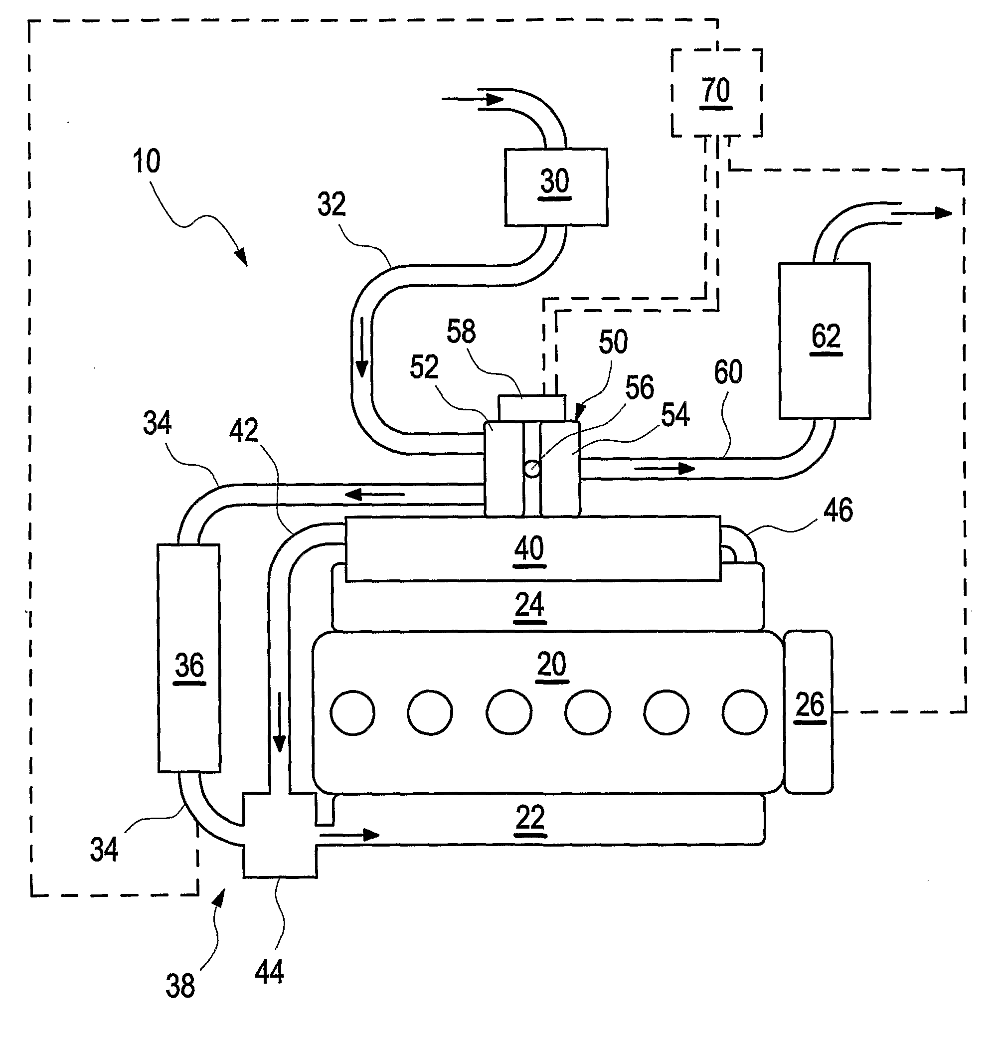
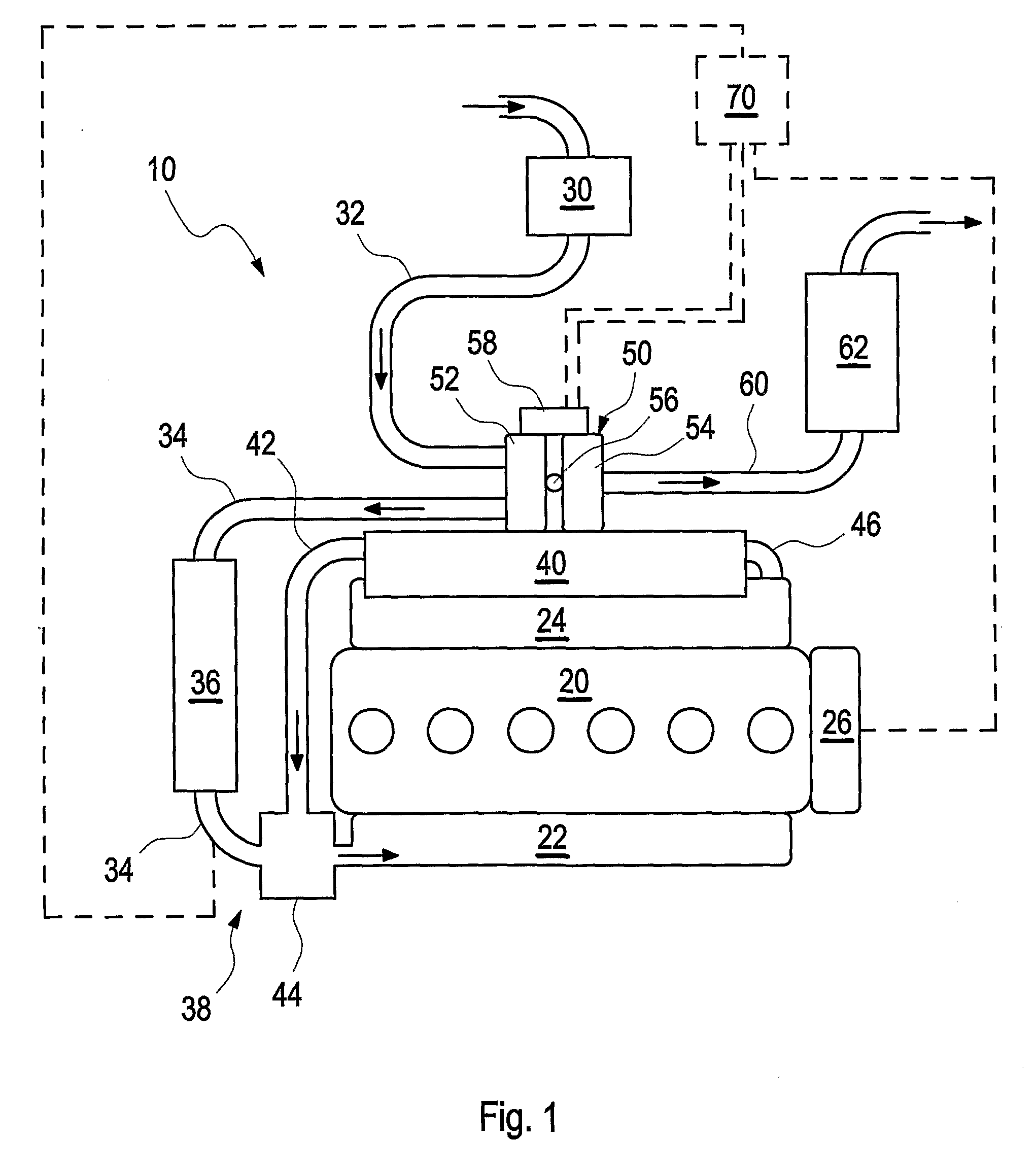
[0026]FIG. 1 depicts schematically an engine 20 of a vehicle (not shown) equipped with a turbocharger 50 comprising a variable geometry turbine 54. Air is fed to an intake manifold 22 of the engine 20 through air pipes 32 and 34. The air pipe 32 is equipped with an air filter 30. Between the air pipes 32 and 34 a compressor 52 of the turbocharger 50 is arranged. A charge air cooler 36 is arranged in the air pipe 34. Compressed air is fed through the air pipe 34 to the charge air cooler 38 into the intake manifold 22.

[0027]The engine 20 is by way of example equipped with an EGR system, wherein exhaust from an exhaust ...


PUM


Abstract

In a method for on board diagnostics for detecting a charge air leakage in a vehicle, air is compressed by a turbine with variable geometry and fed to the combustion engine. Steps are performed of feeding compressed air to the engine without fuel supply to the engine; estimating a boost pressure from a current vane geometry of the variable geometry turbine; measure the actual boost pressure; and comparing the estimated boost pressure with the measured boost pressure.

Description

BACKGROUND AND SUMMARY[0001]The invention relates to a method for on board diagnostics and a system for an on board diagnostics method.[0002]It is known that legal as well as aftermarket demands push the development of more advanced On Board Diagnostics (OBD) to detect malfunctioning devices in vehicles.[0003]In order to detect a charge air leakage in the charge air system of a combustion engine, it is known in the art to compare e.g. a modelled value of the inlet manifold pressure with a measured value. A leakage is detected if the measured value is lower than the modelled value. The model can be based on a couple of known variables such as engine and / or turbine speed, engine torque, amount of fuel injected, actuator position of a variable geometry turbine, advance angle, needle opening pressure of the injector. The advance angle and the needle opening pressure of the injector are mostly excluded from the models as these variables do not change once the engine control strategy is f...

Claims


Application Information

Patent Timeline
Patent Type & Authority Applications(United States)
IPC IPC(8): G01M15/09
CPCF02B37/22F02B39/16F02D41/0007F02D41/221F02D2200/0402F02D2200/0406Y02T10/144F02M25/0707F02M25/0722F02M25/0726G01M15/09G01M15/14Y02T10/40F02D2200/0408F02M26/05F02M26/19F02M26/22Y02T10/12
Inventor WIKNER, STEFAN
Owner VOLVO LASTVAGNAR AB
Why Eureka
Try Eureka