Refrigerating apparatus

a refrigerating apparatus and refrigerating technology, applied in the field of refrigerating apparatus, can solve the problems of oil accumulation, abnormal rise of high pressure side pressure, and inability to use refrigerant based on freon, so as to effectively improve refrigerating ability, smooth oil return to compression means, and enhance performance

Inactive Publication Date: 2011-06-30
PANASONIC INTELLECTUAL PROPERTY MANAGEMENT CO LTD
View PDF16 Cites 25 Cited by
  • Summary
  • Abstract
  • Description
  • Claims
  • Application Information

AI Technical Summary

Benefits of technology

[0060]According to the fifteenth aspect of the present invention, in addition to the thirteenth or fourteenth aspect of the invention, the control means opens the flow path of the oil bypass circuit by the valve device, when the outdoor temperature is lower than the predetermined value, whereby it is possible to prevent the refrigerant from being dissolved in the oil and raising a viscosity thereof and to precisely return the oil from the oil separator to the compression means via the oil bypass circuit which bypasses the oil cooler.
[0061]According to the sixteenth aspect of the present invention, in addition to the thirteenth or fourteenth aspect of the invention, the control means opens the flow path of the oil bypass circuit by the valve device, when the temperature of the oil separator is lower than the predetermined value, whereby it is possible to securely prevent the refrigerant from being dissolved in the oil and raising a viscosity thereof and to return the oil from the oil separator to the compression means via the oil bypass circuit which bypasses the oil cooler.
[0062]When carbon dioxide is used as the refrigerant as in the seventeenth aspect of the present invention, according to the above thirteenth to sixteenth aspects of the invention, it is possible to smoothly return the oil to the compression means. Moreover, it is possible to effectively improve a refrigerating ability and to enhance a performance.
[0063]According to the eighteenth aspect of the present invention, there is provided the refrigerating apparatus in which the refrigerant circuit is constituted of the compression means, the gas cooler, the auxiliary reducing means, the intermediate heat exchanger, the main reducing means and the evaporator. The refrigerating apparatus is configured to branch the refrigerant exiting from the gas cooler into two flows, pass the first refrigerant flow through the first flow path of the intermediate heat exchanger via the auxiliary reducing means, pass the second refrigerant flow through the second flow path of the intermediate heat exchanger and then through the evaporator via the main reducing means, perform heat exchange between the first refrigerant flow and the second refrigerant flow in the intermediate heat exchanger, suck the refrigerant exiting from the evaporator into the low pressure portion of the compression means and suck the first refrigerant flow exiting from the intermediate heat exchanger into the medium pressure portion of the compression means, to obtain the supercritical pressure on the high pressure side. The refrigerating apparatus comprises the exhaust heat recovery heat exchanger including the exhaust heat recovery medium flow path and the refrigerant flow path, and the second refrigerant flow exiting from the gas cooler is passed through the refrigerant flow path of the exhaust heat recovery heat exchanger before entering the intermediate heat exchanger, whereby it is possible to generate hot water by heating the refrigerant of a heat pump unit which is little influenced by an outdoor temperature and which efficiently recovers exhaust heat of the refrigerant flowing through the refrigerant flow path in the exhaust heat recovery heat exchanger to generate the hot water flowing through the exhaust heat recovery medium flow path.
[0064]Moreover, the second refrigerant flow exiting from the gas cooler is passed through the exhaust heat recovery heat exchanger before entering the intermediate heat exchanger. Therefore, when the refrigerating apparatus on a hot water generation side is more utilized, the refrigerant temperature of the second refrigerant flow passing through the intermediate heat exchanger can be lowered, whereby it is possible to decrease the amount of the refrigerant of the first refrigerant flow passing through the intermediate heat exchanger. In consequence, the amount of the refrigerant of the second refrigerant flow can be increased, and the amount of the refrigerant to be evaporated in the evaporator can be increased to improve the efficiency of the refrigerating cycle.
[0065]When carbon dioxide is used as the refrigerant as in the nineteenth aspect of the present invention, according to the above aspects of the invention, it is possible to effectively improve a refrigerating ability and to enhance a performance.

Problems solved by technology

In recent years, in this type of refrigerating apparatus, Freon-based refrigerant cannot be used owing to a natural environmental problem and the like.
Therefore, the amount of the refrigerant to be circulated cannot be regulated in the receiver tank, thereby causing a problem that the high pressure side pressure abnormally rises owing to an excess gas refrigerant in the refrigerant circuit.
Moreover, when oil discharged together with the refrigerant from the compression means circulates together with the refrigerant through the refrigerant circuit, the oil accumulates in a heat exchanger or the like in the refrigerant circuit, and does not easily return to a compressor.
Here, in a case where the oil cooler is installed in an air path provided with the gas cooler and these coolers are air-cooled by the same blower, when the outdoor temperature is low, the oil in the oil cooler is excessively cooled, whereby the refrigerant is easily dissolved in the oil.
The oil including the refrigerant dissolved therein has a raised viscosity and becomes heavy, thereby causing a problem that a return efficiency to the compression means deteriorates.
However, when the efficiency of the hot water supply by use of the exhaust heat recovery heat exchanger deteriorates, it is necessary to dispose a circuit which bypasses the gas cooler.
On the other hand, in a supercritical refrigerant cycle, on conditions that the temperature of the refrigerant at a gas cooler outlet rises owing to a cause such as a high heat source temperature on a gas cooler side (e.g., a high temperature of outside air which is a heat medium subjected to the heat exchange between the medium and the gas cooler), a specific enthalpy at an evaporator inlet increases, thereby causing a problem that a refrigerating effect remarkably deteriorates.
In this case, to acquire a refrigerating ability, the high pressure side pressure needs to be raised, thereby increasing a compression power, to cause a problem that a coefficient of performance also deteriorates.
That is, when the amount of the first refrigerant flow is excessively large, the amount of the second refrigerant flow finally evaporated by the evaporator becomes inadequate.
Conversely, when the amount of the first refrigerant flow is excessively small, the cooling effect by the first refrigerant flow (i.e., the effect of the split cycle) diminishes.
However, when the exhaust heat recovery heat exchanger is disposed on the front stage side of the gas cooler as described above, there is a problem that control of a valve device on a split cycle side becomes complicated in consideration of control on a hot water supply unit side.

Method used


Image

  • Refrigerating apparatus
  • Refrigerating apparatus
  • Refrigerating apparatus

Examples


Embodiment Construction

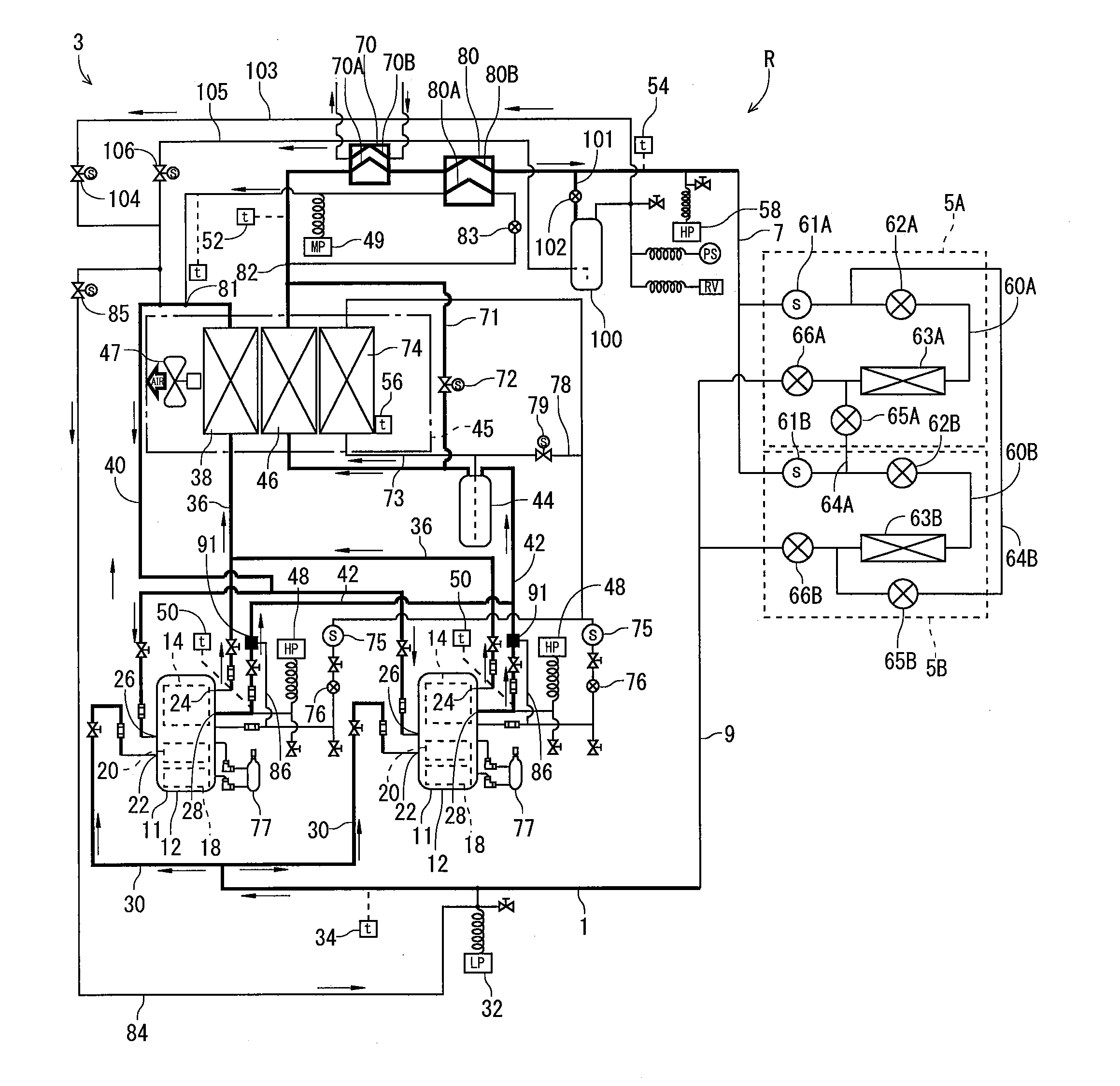
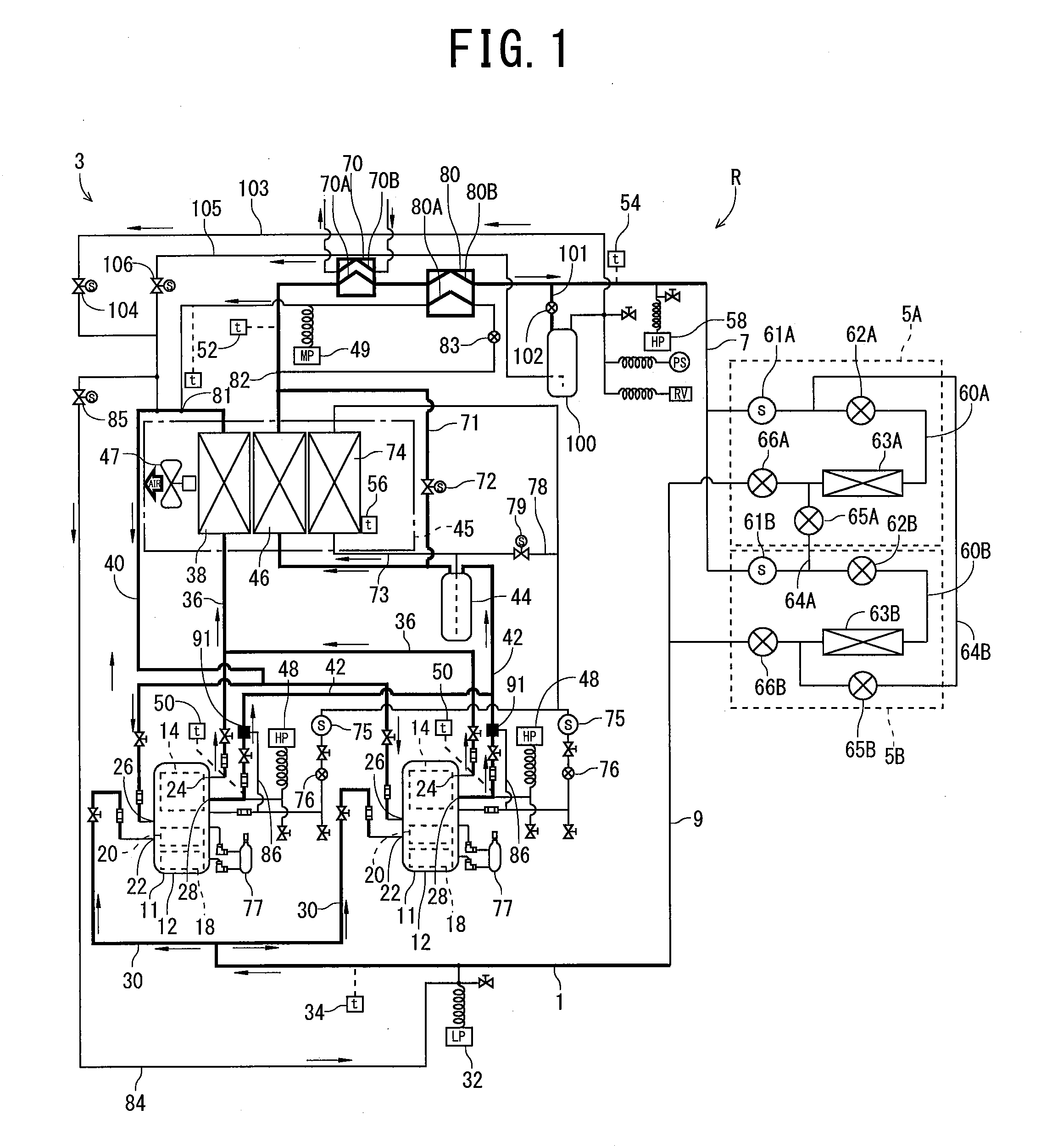
[0071]Hereinafter, an embodiment of the present invention will be described with reference to the drawings. FIG. 1 is a refrigerant circuit diagram of a refrigerating apparatus R according to the embodiment of the present invention. The refrigerating apparatus R in the present embodiment comprises a refrigerator unit 3 and a plurality of showcase units 5A and 5B, and the refrigerator unit 3 is connected to the showcase units 5A and 5B via refrigerant piping lines 7 and 9 to constitute a predetermined refrigerating cycle.

[0072]In this refrigerating cycle, carbon dioxide is used as a refrigerant to obtain a refrigerant pressure which is not lower than a critical pressure of the refrigerant (supercritical) on a high pressure side (a high pressure side pressure). This carbon dioxide refrigerant is an environmentally friendly natural refrigerant which is used in consideration of flammability, toxicity and the like. Moreover, as lubricating oil, existing oil such as mineral oil, alkyl ben...


PUM


Abstract

An object of the present invention is to keep an appropriate amount of a refrigerant to be circulated through a refrigerant circuit and prevent an overload operation of compression means due to high pressure abnormality in a refrigerating apparatus which obtains a supercritical pressure on a high pressure side. The refrigerating apparatus which obtains the supercritical pressure on the high pressure side comprises a refrigerant amount regulation tank connected to the refrigerant circuit on the high pressure side via a communicating circuit; a communicating circuit which connects the upper part of this tank to a medium pressure region of the refrigerant circuit; a communicating circuit which connects the lower part of the tank to the medium pressure region of the refrigerant circuit; an electromotive expansion valve of the communicating circuit; an electromagnetic valve of the communicating circuit; an electromagnetic valve of the communicating circuit; and control means for controlling these valves to collect a refrigerant circulated through the refrigerant circuit in the tank and discharging the refrigerant to the refrigerant circuit.

Description

BACKGROUND OF THE INVENTION[0001]The present invention relates to a refrigerating apparatus in which a refrigerant circuit is constituted of compression means, a gas cooler, reducing means and an evaporator to obtain a supercritical pressure on a high pressure side.[0002]Heretofore, in this type of refrigerating apparatus, a refrigerating cycle is constituted of the compression means, the gas cooler, the reducing means and the like, and a refrigerant compressed by the compression means releases heat in the gas cooler, has a pressure thereof reduced by the reducing means, and is then evaporated in the evaporator, to cool ambient air by the evaporation of the refrigerant at this time. In recent years, in this type of refrigerating apparatus, Freon-based refrigerant cannot be used owing to a natural environmental problem and the like. Therefore, an apparatus has been developed in which carbon dioxide as a natural refrigerant is used as an alternative of the Freon-based refrigerant. It ...

Claims


Application Information

Patent Timeline
Patent Type & Authority Applications(United States)
IPC IPC(8): F25B49/00
CPCF25B1/10F25B9/008F25B31/004F25B45/00F25B2309/061F25B2700/2106F25B2347/021F25B2400/075F25B2400/13F25B2400/16F25B2600/17F25B2339/047
Inventor MIHARA, KAZUHIKOSASAKI, HIDETAKAHASEGAWA, SETSUKAWAKUBO, KENOTAKE, MASAHISA
Owner PANASONIC INTELLECTUAL PROPERTY MANAGEMENT CO LTD
Why Eureka
Try Eureka