Conductive polymer foams, method of manufacture, and uses thereof

Inactive Publication Date: 2011-06-30
ROGERS CORP
View PDF73 Cites 41 Cited by
  • Summary
  • Abstract
  • Description
  • Claims
  • Application Information

AI Technical Summary

Benefits of technology

[0007]Further disclosed is a layer comprising a polymer foam, the polymer foam layer having an unabraded first surface and an opposite, second surface; and a plurality of electrically conductive particles aligned into mutually isolated columns having a first end and a second end, wherein the electrically conductive particles essentially continuously span

Problems solved by technology

One difficulty with currently available methods and materials is that the addition of the high levels of conductive filler(s) sufficient to achieve high conductivity affects the compressibility and proc

Method used


Image

  • Conductive polymer foams, method of manufacture, and uses thereof
  • Conductive polymer foams, method of manufacture, and uses thereof
  • Conductive polymer foams, method of manufacture, and uses thereof

Examples


example 1

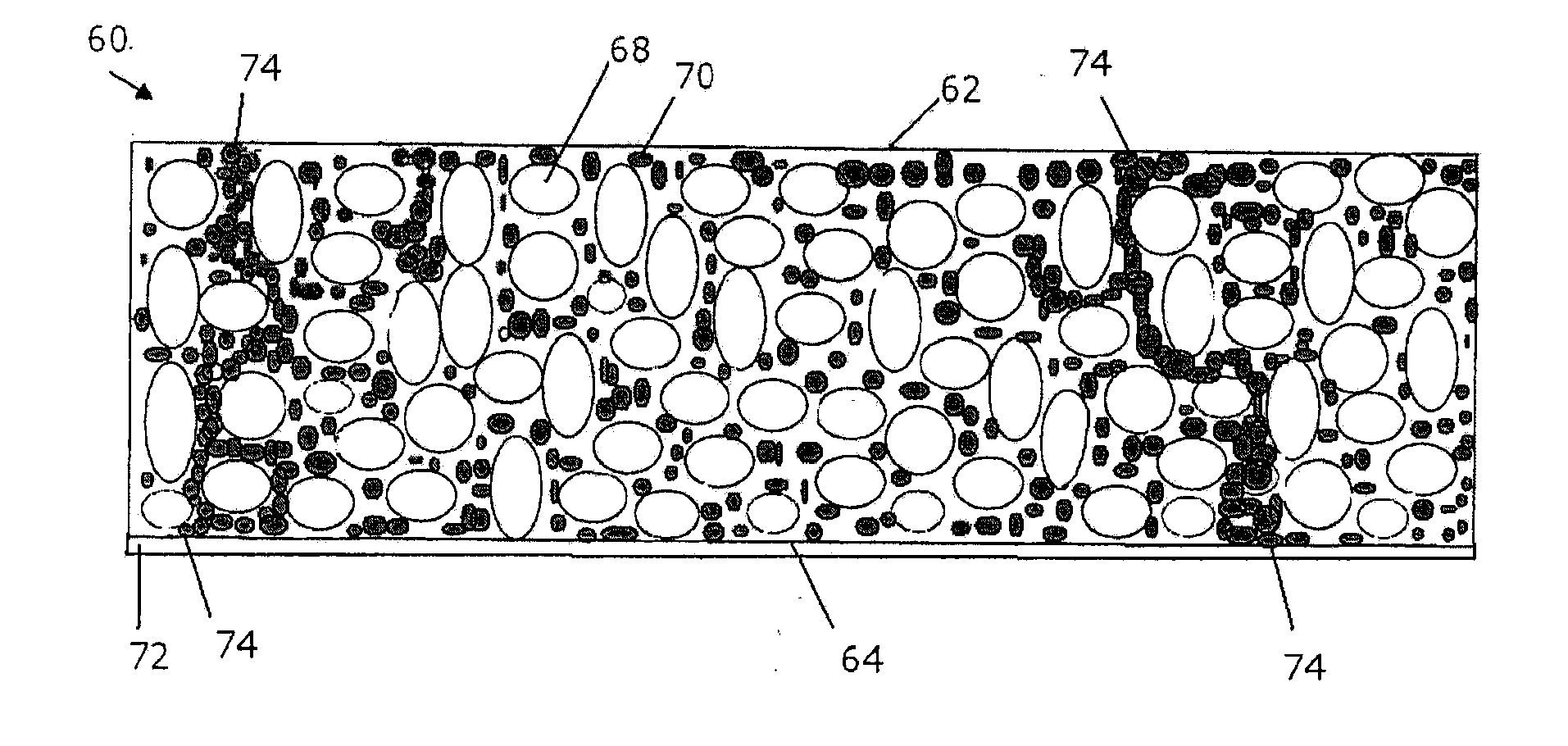
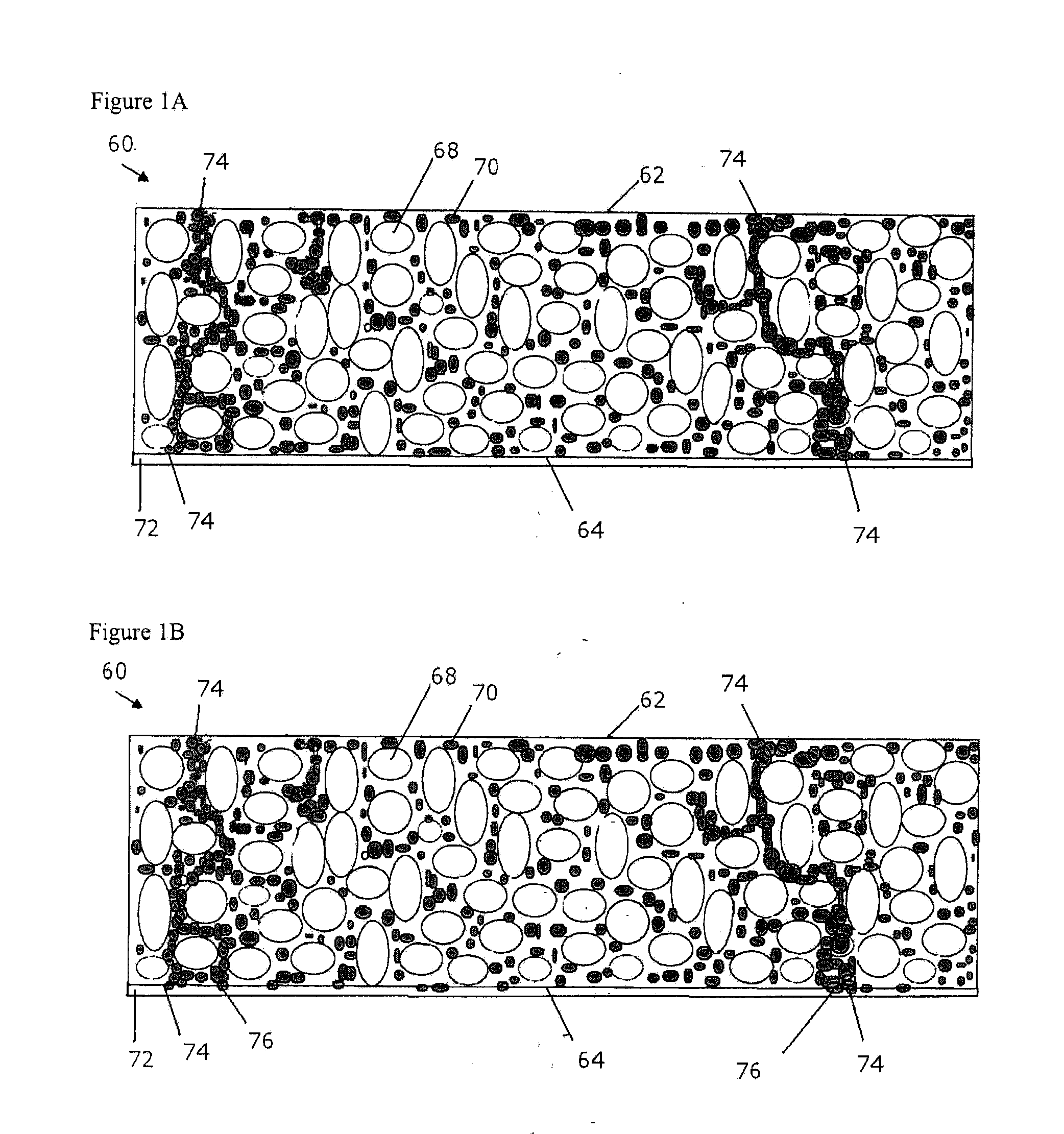
[0115]An evaluation of nickel and nickel-coated ceramic microspheres as conductive fillers in a silicone foam was performed. Silicones (Dow Corning Silicone 8137 and NUSIL 6033 from Nusil Technology LLC), the filler microspheres, and silicone cure inhibitor (1-octyn-3-ol from Aldrich Chemical Co.) were mixed in a Flaktek speed mixer, cast on a PET film with a controlled thickness, and were placed in an oven exposed to an adjustable magnetic field. In general, the chemically blown and cured foams had a thickness of 70 to 80 mils (1778 to 2032 micrometers).

[0116]The results in Table 1 show that even under a magnetic field as strong as 1200 Gauss, no conductivity was observed in the thick layers of the cured foam.

TABLE 1Run No.1234567Magnetic field, Gauss250 250 1000 1000 1200 1200 1200 Casting thickness, mil10202020202020Oven temperature, ° C.23232323232323Oven residence time, min 5 5 5 5101010Top carriernononononononoSi formulation A / B, gras33 / 3.333 / 3.333 / 3.333 / 3.333 / 3.333 / 3.333 / 3.3I...

example 2

[0117]Table 2 shows the results of additional runs using 100% nickel microspheres. Formulations were cast at a thickness of 18 to 40 mil (457 to 1016 micrometers) to prepare foam samples.

TABLE 2Run No.12345678910111213Magnetic field, Gauss1000100010001000100010001000100010001000100010001000Casting thickness, mil20204040402718181818181827Oven temp, ° C.60606060606060606060606060Oven residence time, min101055555555555With top carriernononoyesyesyesyesyesyesyesyesyesyesSi formulation, A / B, gras33 / 3.333 / 3.333 / 3.333 / 3.333 / 3.333 / 3.333 / 3.333 / 3.350 / 550 / 533 / 3.333 / 3.333 / 3.3Inhibitor, drops4444444466444(about 40 mg)Filler sphere size,45-7545-7545-7545-7545-7545-7545-7545-7545-7545-7532-4532-4532-45micrometerFiller loading, grams18243030303033505550506060Nickel column formationyesyesyesyesyesyesyesyesyesyesyesyesyesThickness, mil2123551031259849464647474172Density, PCF38.437.330.23126.12224.726.928.330.830.838.139.9ConductivitynononononononononononononoFoam qualitypoorpoorpoorgoodgoodgoodgoodgo...

example 3

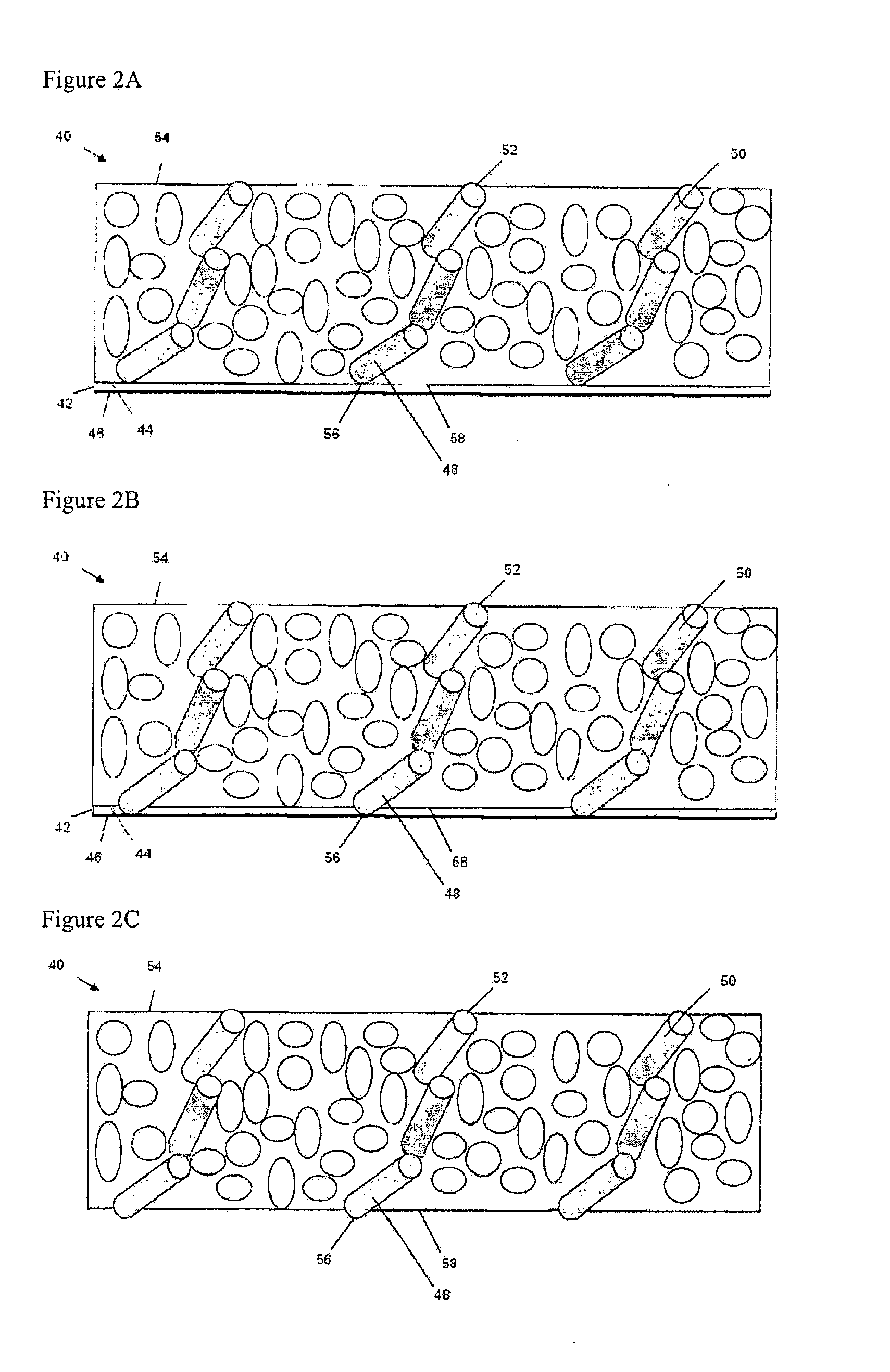
[0119]Thinner foams were prepared using 100% Ni spheres or silver-coated nickel spheres, both with and without a top carrier as indicated. The premix was cooled in a refrigerator. The results are shown in Table 3A.

TABLE 3ARun No.1a1b2a2b3a3b4a4bMagnetic field, Gauss500500250250250250250250Casting thickness, mil5555551010Oven temp, ° C.5555555550505050Oven residence time, min55555555With top carriernoyesnoyesnoyesnoyesSubstratePETPETPETPETPETPETPETPETSi formulation A / B, gras33 / 3.333 / 3.333 / 3.333 / 3.333 / 3.333 / 3.333 / 3.333 / 3.3Inhibitor, drops (about 40 mg)44444444Filler sphere size, micrometer45-7545-7545-7545-7545-7545-7575-90*75-90*Filler loading, grams4848484848484848Filler column formationyesyesyesyesyesyesyesyesThickness, mil813613.5614614Density, PCF72.335.497.734.2102.53493.535Conductivitynoyesnoyesn / tn / tyesyes*Silver-coated nickel spheresn / t: not tested

[0120]As can be seen from the results in Table 3A, nickel column formation was observed in all runs. The cured foams had a thickne...


PUM

PropertyMeasurementUnit
Pressureaaaaaaaaaa
Angleaaaaaaaaaa
Fractionaaaaaaaaaa

Abstract

A polymer foam layer is disclosed, comprising a polymer foam and a plurality of electrically conductive particles dispersed within the polymer foam, polymer foam layer having an unabraded first surface and an opposite, second surface, wherein the electrically conductive particles essentially continuously span the polymer foam layer, and a portion of the electrically conductive particles are exposed at the first surface of the layer and another portion of the electrically conductive particles are exposed at the second surface. The foams are useful as gaskets for electromagnetic shielding, grounding pads, battery contact conductive spring elements, and the like.

Description

CROSS-REFERENCE TO RELATED APPLICATION[0001]This application claims the benefit of U.S. Provisional Application Ser. No. 61 / 290,688 filed Dec. 29, 2009 and is a continuation-in-part of co-pending U.S. application Ser. No. 12 / 404,566 filed on Mar. 16, 2009 and published as U.S. Publication. No. 2009 / 0226696, which is a continuation-in-part of U.S. application Ser. No. 12 / 186,093 filed on Aug. 5, 2008, which is a continuation-in-part of U.S. application Ser. No. 12 / 027,018 filed on Feb. 6, 2008 and is now U.S. Pat. No. 7,815,998, which claims the benefit of U.S. Provisional Application No. 60 / 888,360 filed on Feb. 6, 2007, all of which are incorporated herein by reference in their entirety.BACKGROUND[0002]This disclosure relates to electrically conductive polymers, and methods of manufacture thereof, as well as articles comprising the polymers.[0003]Electrically conductive polymer foams are of utility in a wide variety of applications, including as electrical contacting devices, in se...

Claims


Application Information

Patent Timeline
IPC IPC(8): H01B1/22H01B1/12H01F1/26B05D5/12H01F1/00H01F41/24
CPCY10T156/1195C08J2375/04C08J2383/04C08J9/0066C08K3/0091C08K9/02C08K3/08C08K3/11
Inventor SOONG, SHARON Y.
Owner ROGERS CORP
Why Eureka
Try Eureka