Distributed vision system with multi-phase synchronization

a vision system and multi-phase technology, applied in the field of multi-camera vision systems, can solve the problems of difficult to determine if a given result pertains to a specific inspection cycle or another inspection cycle, render synchronizing the results even more difficult, and prove very difficult and time-consuming to provide reliable results, etc., to achieve rapid recovery and increase timing accuracy

Active Publication Date: 2011-06-30
COGNEX CORP
View PDF14 Cites 32 Cited by
  • Summary
  • Abstract
  • Description
  • Claims
  • Application Information

AI Technical Summary

Benefits of technology

[0014]This invention overcomes disadvantages of the prior art by providing a fault-tolerant system and method for synchronizing the inspection results of a scalable plurality of vision system processors that allows for rapid recovery from a variety of problems, such as missed triggers, extra triggers and power loss at one or more system processors. In an illustrative embodiment, the invention provides a system and method for synchronization of vision system inspection results produced by each of a plurality of processors that includes a first bank (that can be a “master” bank) containing a master vision system processor and at least one slave vision system processor. At least a second bank (that can be one of a plurality of “slave” banks) contains a master vision system processor and at least one slave vision system processor. Each vision system processor in each bank generates results from one or more images acquired and processed in a given inspection cycle. In an embodiment, processors are each associated with a given camera. In other embodiments the processors in one or more processor banks are associated with one or more shared cameras. The inspection cycle can be based on an external trigger or other trigger signal, and it can enable some or all of the processors/banks to acquire and process images at a given time/cycle. In a given cycle, each of the multiple banks can be positioned to acquire an image of a respective region of a plurality of succeeding regions on a moving line. The next cycle acquires and processes images of a next grouping of objects or regions along the line—providing processing time between each movement of the groups of parts into the field of view of the each camera. A synchronization process (a) generates a unique identifier and that passes a trigger signal with the unique identifier associated with the master processor in the first bank to each of the slave processor in the master bank and each of the master and slave processor and (b) receives consolidated results via the master processor of ...

Problems solved by technology

Since each inspection result can have an unpredictable processing time, it is sometimes difficult to determine if a given result pertains to a specific inspection cycle or another inspection cycle.
In applications that require substantial processing power it may be necessary to distribute a single inspection task among multiple processors, which renders synchronizing the results even more challenging.
Nevertheless, it proves very challenging and time-consuming to provide a reliable PLC application that correctly synchronizes results at high speed and can recover from many types of transient problems that may affect synchronization of the results of a given inspection cycle.
Additionally, placing the burden of synchronization on the PLC adds cost and complexity to the application, and makes it more difficult to maintain due to the “vision logic” in the PLC program that typically also controls the process equipment.
However, this approach suffers from a lack of scalability.
As more cameras are added, additional burden is placed on the processor, which is contemporaneously receiving a plurality of images for machine-vision processing.
In some cases it is possible to add co-processors to increase the machine vision processing capability, but it offers very limited scala...

Method used


Image

  • Distributed vision system with multi-phase synchronization
  • Distributed vision system with multi-phase synchronization
  • Distributed vision system with multi-phase synchronization

Examples


Embodiment Construction

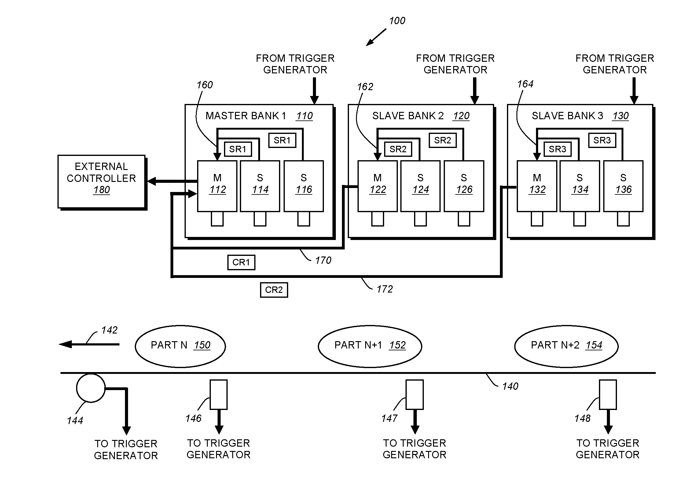
[0023]FIG. 1 is a schematic diagram of an exemplary arrangement of a multi-phase, multi-processor machine vision system 100 according to an illustrative embodiment. This arrangement 100 is exemplary of a wide variety of possible camera arrangements according to illustrative embodiments. The number of cameras and their placement is widely variable. In this example, each camera is assumed to contain an independent processing device. In other arrangements the processing devices may be physically separated from the cameras, and any given processing device may process images from one or more cameras. Likewise, cameras can be physically or optoelectronically manipulated by a motion control device (blocks 202 in FIGS. 2 and 302 in FIG. 3) to allow variable acquisition of images from multiple or variable locations. As shown, the exemplary arrangement includes three vision system processor banks 110, 120, 130. In this exemplary arrangement, the processors are each associated with a camera / se...


PUM


Abstract

This invention provides a system and method for synchronization of vision system inspection results produced by each of a plurality of processors that includes a first bank (that can be a “master” bank) containing a master vision system processor and at least one slave vision system processor. At least a second bank (that can be one of a plurality of “slave” banks) contains a master vision system processor and at least one slave vision system processor. Each vision system processor in each bank generates results from an image acquired and processed in a given inspection cycle. The inspection cycle can be based on an external trigger or other trigger signal, and it can enable some or all of the processors/banks to acquire and process images at a given time/cycle. In a given cycle. each of the multiple banks can be positioned to acquire an image of a respective region of a plurality of succeeding regions on a moving line. A synchronization process (a) generates a unique identifier and that passes a trigger signal with the unique identifier associated with the master processor in the first bank to each of the slave processor in the master bank and each of the master and slave processor and (b) receives consolidated results via the master processor of the second bank, having the unique identifier and consolidated results from the results from the first bank. The process then (c) consolidates the results for transmission to a destination if the results are complete and the unique identifier of each of the results is the same.

Description

FIELD OF THE INVENTION[0001]This invention relates to vision systems for use in inspecting parts, objects and surfaces, and more particularly to multi-camera vision systems.BACKGROUND OF THE INVENTION[0002]The use of advanced vision systems (also termed “machine vision”) and their underlying software is increasingly employed in a variety of manufacturing and quality control processes. Machine vision enables quicker, more accurate and repeatable results to be obtained in the production of both mass-produced and custom products. Typical machine vision systems include one or more cameras (typically having solid-state charge couple device (CCD) or CMOS-based imaging elements) directed at an area of interest, a frame grabber / image processing elements that capture and transmit CCD images, one or more computers or onboard processing devices, and a user interface for running the machine vision software application and manipulating the captured images, and appropriate illumination on the are...

Claims


Application Information

Patent Timeline
IPC IPC(8): H04N5/228
CPCH04N5/232H04N5/23206H04N21/4302H04N21/242H04N5/247H04N23/662H04N23/90
Inventor MCCLELLAN, JAMES R.
Owner COGNEX CORP
Why Eureka
Try Eureka