Laser treatment system and method for producing thermal cavities and energy droplets

a laser treatment system and thermal cavity technology, applied in the field of fiber laser systems, can solve the problems of small tissue damage, and achieve the effect of minimizing or preventing any significant damage to adjacent tissu

Inactive Publication Date: 2011-06-30
TANKOVICH NIKOLAI +1
View PDF4 Cites 26 Cited by
  • Summary
  • Abstract
  • Description
  • Claims
  • Application Information

AI Technical Summary

Benefits of technology

[0008]In preferred embodiments the process includes the steps of illuminating a first region of skin for a first time period with a preheat laser beam with sufficient energy to heat the first region to a temperature-time profile that is close to but below a temperature-time profile that would cause tissue damage. This first region is referred to as a “thermal cavity”. A tiny sub-region of skin located below the skin surface and within the first region of skin is illuminated for a second time period with one or more energy droplet laser beams adapted to apply an additional quantity of heat to the sub-region of skin to increase its temperature-time profile to a temperature-time profile in excess of a temperature-time profile sufficient to cause tissue damage within the sub-region. The additional quantity of heat in the sub-region is referred to as an “energy droplet”. As a result tissue damage in the sub-region stimulates the healing process that subsequently extends beyond the region damaged to produce rejuvenated skin tissue.
[0009]Thus tiny regions of tissue are damaged while minimizing or preventing any significant damage to adjacent tissue. Preferred embodiments include a laser hand piece designed to deliver skin surface cooling and the laser beam from the first laser to create the thermal cavity and the laser beams form the second laser a target volume to create the energy droplets. In preferred embodiments the surface cooling is provided with a flow of cold air and the number of laser beams from the second laser are six laser beams. The cooling air in preferred embodiments is at about 0 to 3° C. and may be provided with a commercial off-the-shelf cooling air unit or with simpler unit consisting of a blower unit, an accumulator and a tube coiled in an ice water bath. Other techniques for cooling the skin surface can be used. A simple technique that can be used to pre-cool the skin surface is a metal container containing ice which is pressed against the skin surface prior to laser illumination. The two laser beams can be provided by a

Problems solved by technology

As a result tissue damage in the sub-region stimulates the healing process that subsequently extends beyond the region damaged to produce

Method used


Image

  • Laser treatment system and method for producing thermal cavities and energy droplets
  • Laser treatment system and method for producing thermal cavities and energy droplets
  • Laser treatment system and method for producing thermal cavities and energy droplets

Examples


Embodiment Construction

Preferred Embodiments

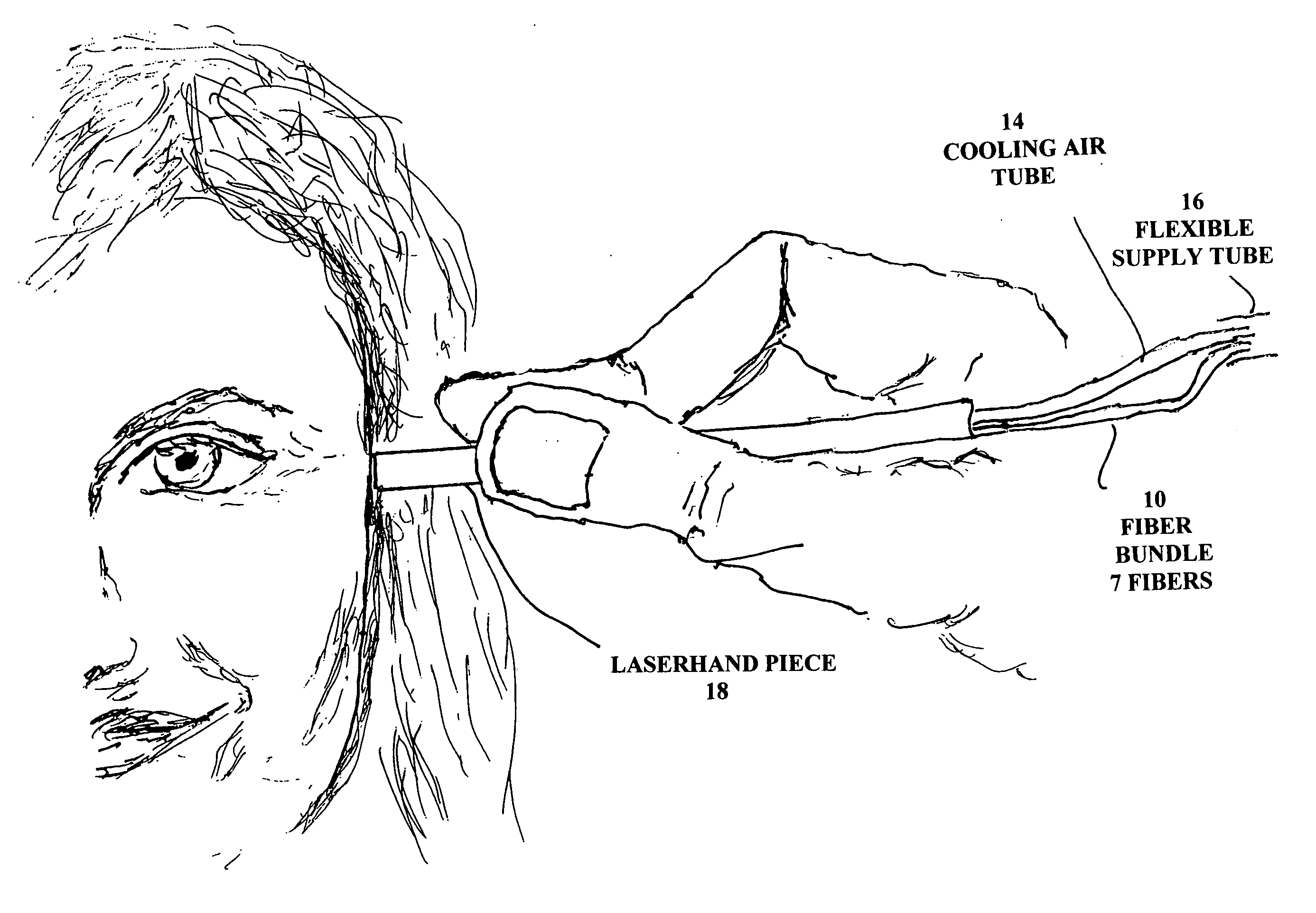
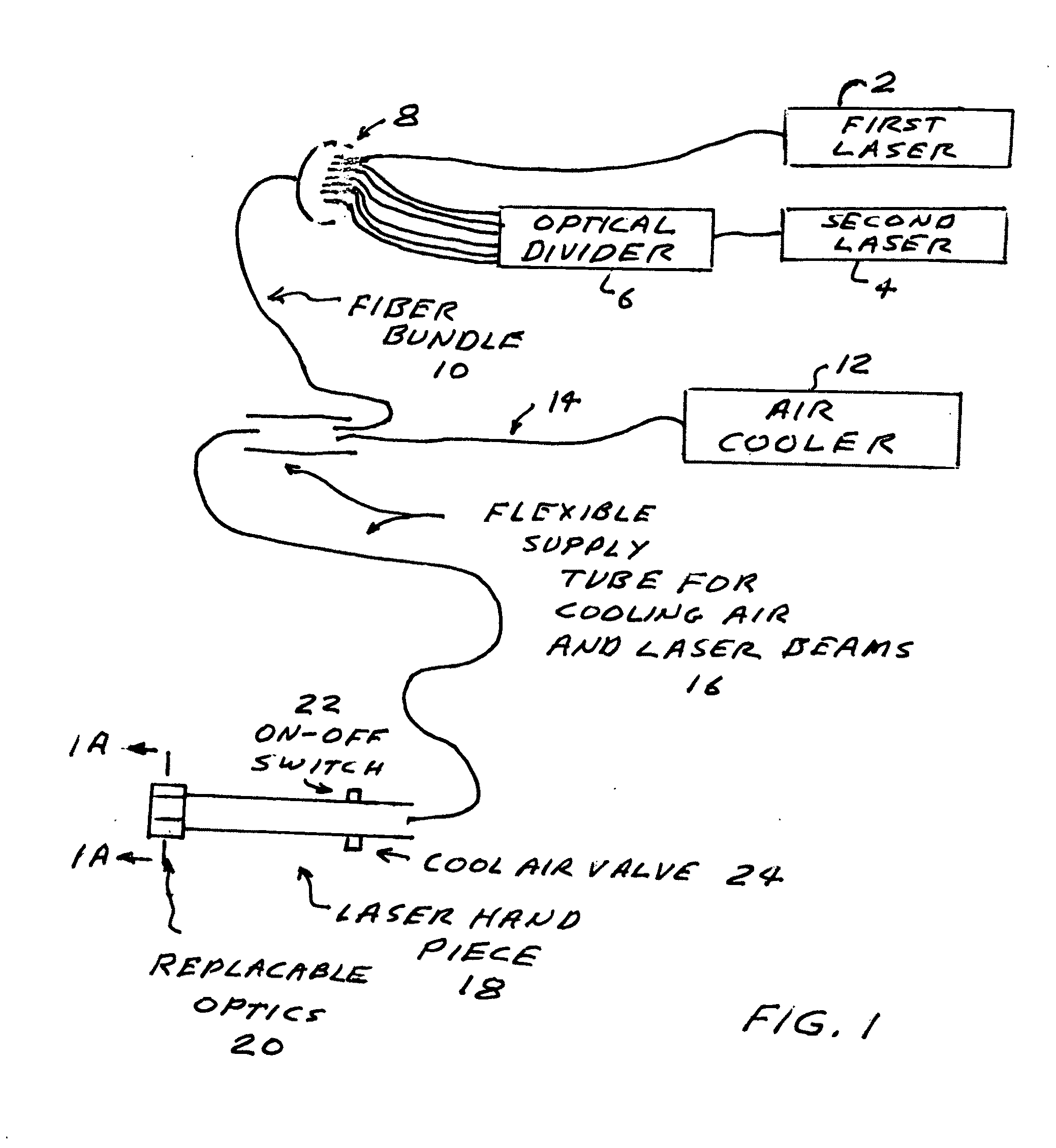
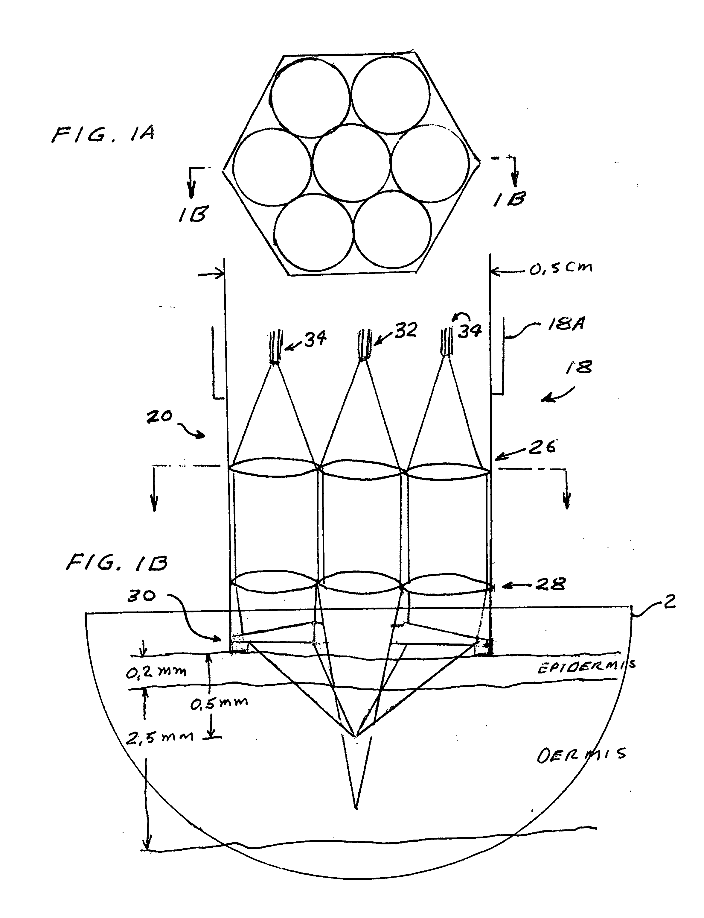
[0018]FIGS. 1 through 3 show features of preferred embodiments of the present invention. As shown in FIG. 2 the embodiment includes first laser source 2, second laser source 4, an optical divider 6 for dividing the output of the second laser source into six laser beams each of the six beams are directed into separate optical fibers which fibers are combined in combiner 8 with a single fiber carrying the output of the first laser source 2. The seven fibers are transported in a fiber bundle 10 which is combined cooling air tube 14 carrying approximately zero degrees centigrade cooling air which is cooled air cooler 12. Flexible supply tube 16 carries the seven laser beams and the cooling air to laser hand piece 18 which includes a cooling air valve 24 and a laser on-off switch 22. The laser hand piece 18 includes a replaceable optics unit 20. Details of replaceable optics unit are shown in FIGS. 1A and 1B.

[0019]The replaceable optics unit 20 fits in the body 18A i...


PUM


Abstract

A laser process for tissue treatment. Preferred embodiments include features for producing a first laser beam and a second laser beam and a skin cooler for cooling the surface of a region of skin. The system is designed to utilize the first laser beam for heating a volume of skin tissue below the cooled surface region to a temperature below skin tissue damage threshold. This volume of skin tissue is called a “thermal cavity”. The second laser beam is divided into a plurality of separate laser beams that are directed through separate optical fibers and via separate paths through skin tissue to a single tiny volume of skin tissue within the thermal cavity to heat that tiny volume to a temperature above the damage threshold. This tiny volume is called an energy droplet. Thus tiny regions of tissue are damaged while minimizing or preventing any significant damage to adjacent tissue.

Description

CROSS REFERENCE TO RELATED APPLICATIONS[0001]This application is a continuation-in-part of U.S. patent application Ser. No. 10 / 890,076 filed Jul. 12, 2004. That application especially the background section and the description of the first preferred embodiment and related drawings are incorporated herein by reference.FIELD OF THE INVENTION[0002]This invention relates to fiber laser systems and in particular to fiber lasers for skin treatment.BACKGROUND OF THE INVENTIONFiber Lasers[0003]Fiber lasers are lasers made using optical fibers. Light emitting atoms are doped into the core of an optical fiber that confines the light the atoms emit. Optical fibers with mirrors or other reflectors on each end can serve as oscillators. Optical fiber amplifiers are widely used and are similar to the fiber lasers but in the amplifiers there is no oscillation.Wavelength Selection[0004]Some wavelengths are very preferentially absorbed in a particular type of tissue when the tissue contains a particu...

Claims


Application Information

Patent Timeline
IPC IPC(8): A61B18/20
CPCA61B18/20A61B18/203A61B18/22A61B2018/00029H01S3/113A61B2018/00458A61B2018/2035A61B2018/208H01S3/0675A61B2018/00452A61B2018/0047A61B2018/00714
Inventor TANKOVICH, NIKOLAILUKASHEV, ALEXEI
Owner TANKOVICH NIKOLAI
Why Eureka
Try Eureka