

Reconstructing an Acoustic Field
- Summary
- Abstract
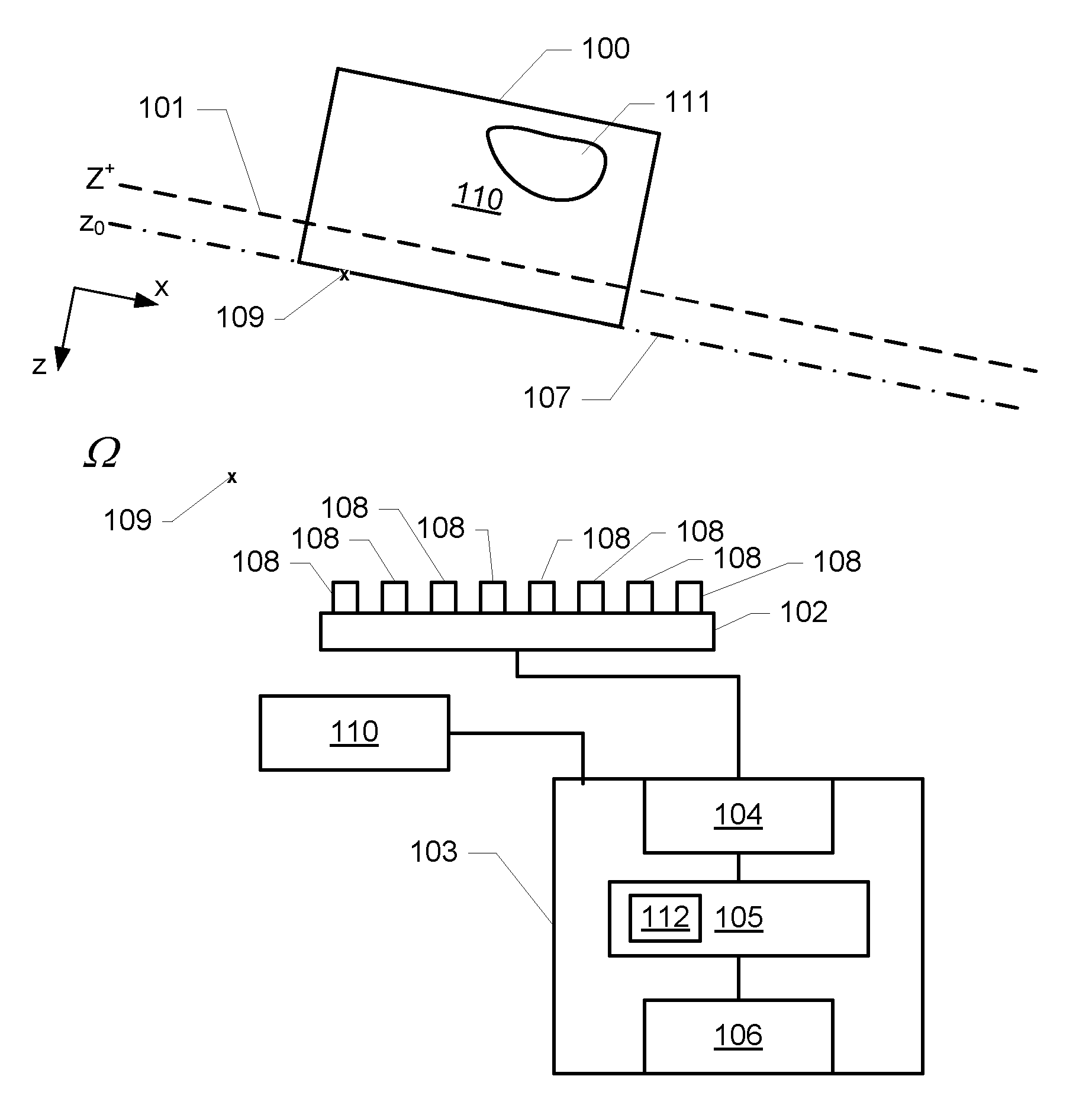
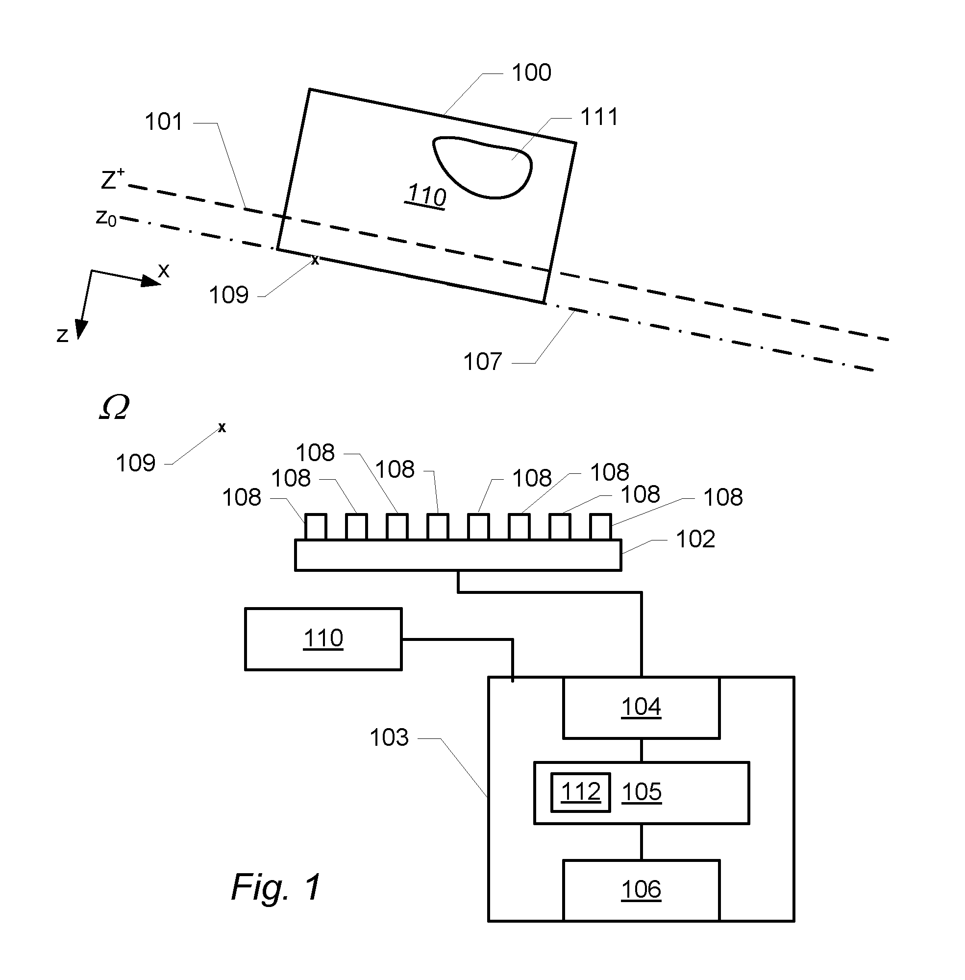
- Description
- Claims
- Application Information
AI Technical Summary
Benefits of technology
Problems solved by technology
Method used
Image

Examples
examples
Numerical Investigation of Prediction Errors
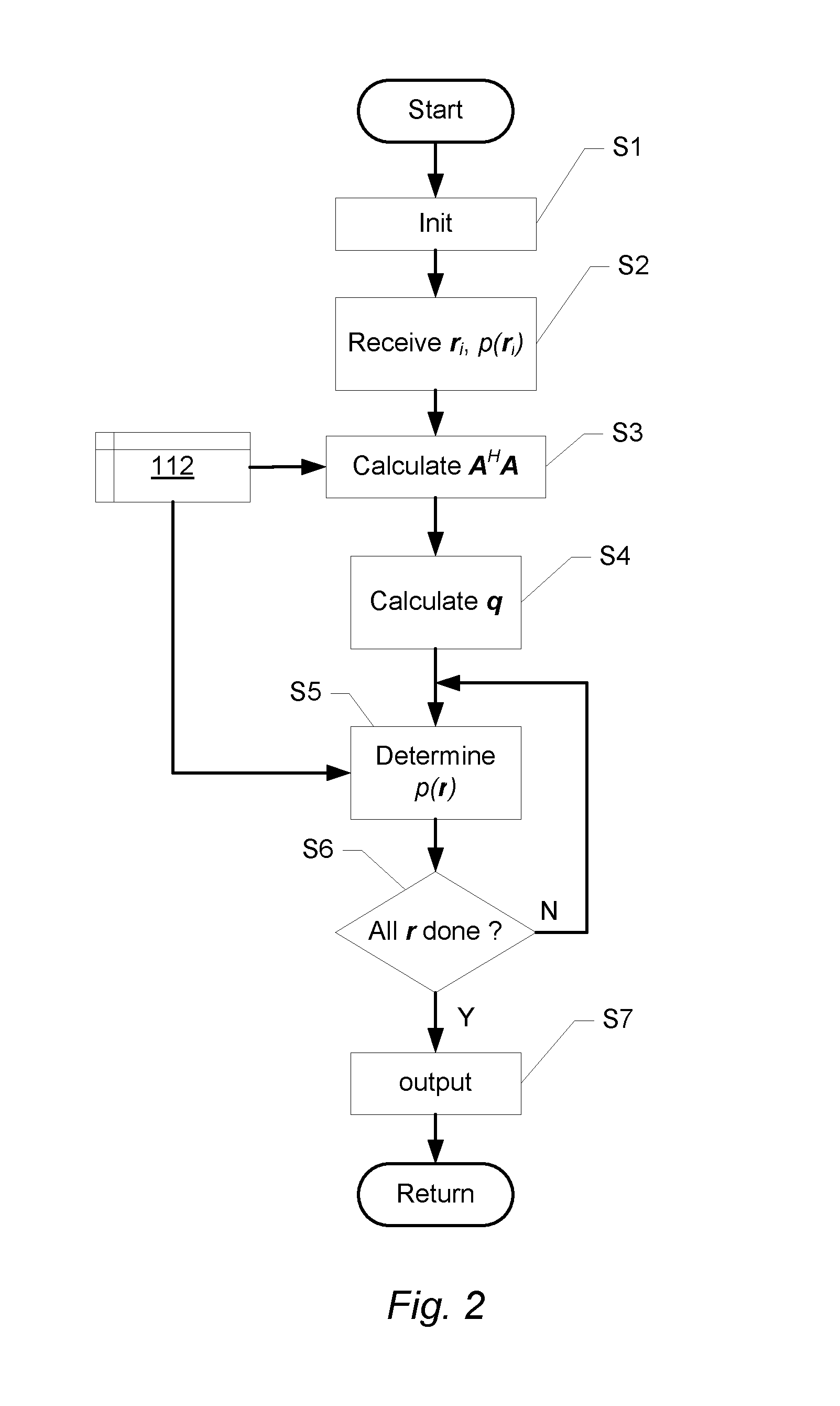
[0155]In the following, information about the regions of validity of the predictions of the method described herein for a couple of typical array geometries and as a function of frequency will be summarized.
[0156]Measurement errors will not be considered, and methods for automatic determination of the regularization parameter (GCV, L-curve, . . . ) will not be investigated either. For the purpose of the present example, the regularization parameter ε to be used in Eq. (11) and (26) is determined from a specified dynamic range D (Signal-to-Noise-Ratio) using the following formula (see e.g. R. Steiner and J. Hald, “Near-field Acoustical Holography without the errors and limitations caused by the use of spatial DFT,” Intern. J. Acoust. Vib. 6, 83-89 (2001)):
ε=[AHA]ii10−D / 10, (44)
where [AHA]ii is a diagonal element of the matrix AHA. This relation was derived for a planar array and free-field conditions, in which case all diagonal elements ar...
example a
Region of Accurate Pressure Representation in a Measurement Plane
[0157]We start with an investigation of the generic inherent error distributions in the array plane z=0 of two different irregular planar array designs. Both have a diameter equal to 0.75 m and both are optimized for beamforming application up to at least 20 kHz. One is a Spoke Wheel array consisting of 13 identical 6-element line arrays arranged as spokes in a wheel, see FIG. 5. The other is a Sector Wheel Array (see e.g. J. Hald, “Array designs optimized for both low-frequency NAH and high-frequency beamforming”, Proceedings of Inter-Noise 2004) consisting of 7 identical angular sectors with 12 microphones irregularly but uniformly distributed in each sector. The uniform distribution of the sector wheel array was maintained during the array geometry optimization in order to obtain good performance in connection with SONAH applications. Since the arrays are planar, we assume free field conditions and use only a single...
example b
Region of Accurate Pressure Representation Outside the Measurement Plane
[0159]We now turn to an investigation of the region of accurate sound pressure prediction in a plane normal to the array plane. Instead of the irregular arrays designed for beamforming we consider regular 8×8 element single layer (8×8×1) and dual layer (8×8×2) arrays with 3 cm element spacing in the x- and y-directions, covering the area 0≦x≦21 cm, 0≦y≦21 cm. Both array types have a microphone layer in the xy-plane z=0, and the dual layer array has an additional identical layer at z=3 cm. We look at the relative sound pressure prediction error in the xz-plane y=10.5 cm, which is a symmetry plane of the arrays. Just like for the irregular planar arrays we choose for the single layer regular array a virtual source plane at a distance from the array equal to two times the array element spacing, i.e. z+=−6 cm. For the dual layer array we choose the same distance to the front virtual source plane and a distance to th...
PUM
 Abstract
Description
Claims
Application Information