Imaging method and apparatus

a technology of imaging and method, applied in the direction of spectroscopy, catheters, diagnostics using spectroscopy, etc., can solve the problems of not achieving cellular or subcellular resolution, and achieve the effect of high tissue magnification, fine surgical procedures, and high magnification

Inactive Publication Date: 2011-07-07
CARL ZEISS MEDITEC INC +2
View PDF7 Cites 10 Cited by
  • Summary
  • Abstract
  • Description
  • Claims
  • Application Information

AI Technical Summary

Benefits of technology

[0006]The apparatus may comprise an endomicroscope or other endomicroscopic apparatus. An endomicroscope is high resolution microscope capable of cellular, subcellular and surface and subsurface imaging, such as a miniature confocal microscope or other scanning microscope probe. The apparatus may be adapted to be used with a macroscopic visualization apparatus such as an operating microscope. As will be understood by those in the art, an operating microscope is the main visualization tool of a microsurgeon. It provides high magnification of tissue and thus allows very fine surgical procedures to be performed, though does not achieve cellular or subcellular resolution. An operating microscope is typically a direct viewing binocular device with a continuous passive optical path from tissue to observer. Thus, while an operating microscope is commonly referred to as a ‘microscope’, it should not be confused with an endomicroscope or an apparatus according to the present invention, which are specific types of microscopes that operate with at least an order of magnitude higher magnification than an operating microscope. The apparatus may be configured to orient an image collected with the probe so as to correspond to a normal field of view of a macroscopic visualization apparatus. The invention also provides an operating microscope that includes an imaging apparatus as described above.

Problems solved by technology

It provides high magnification of tissue and thus allows very fine surgical procedures to be performed, though does not achieve cellular or subcellular resolution.

Method used


Image

  • Imaging method and apparatus
  • Imaging method and apparatus
  • Imaging method and apparatus

Examples


Embodiment Construction

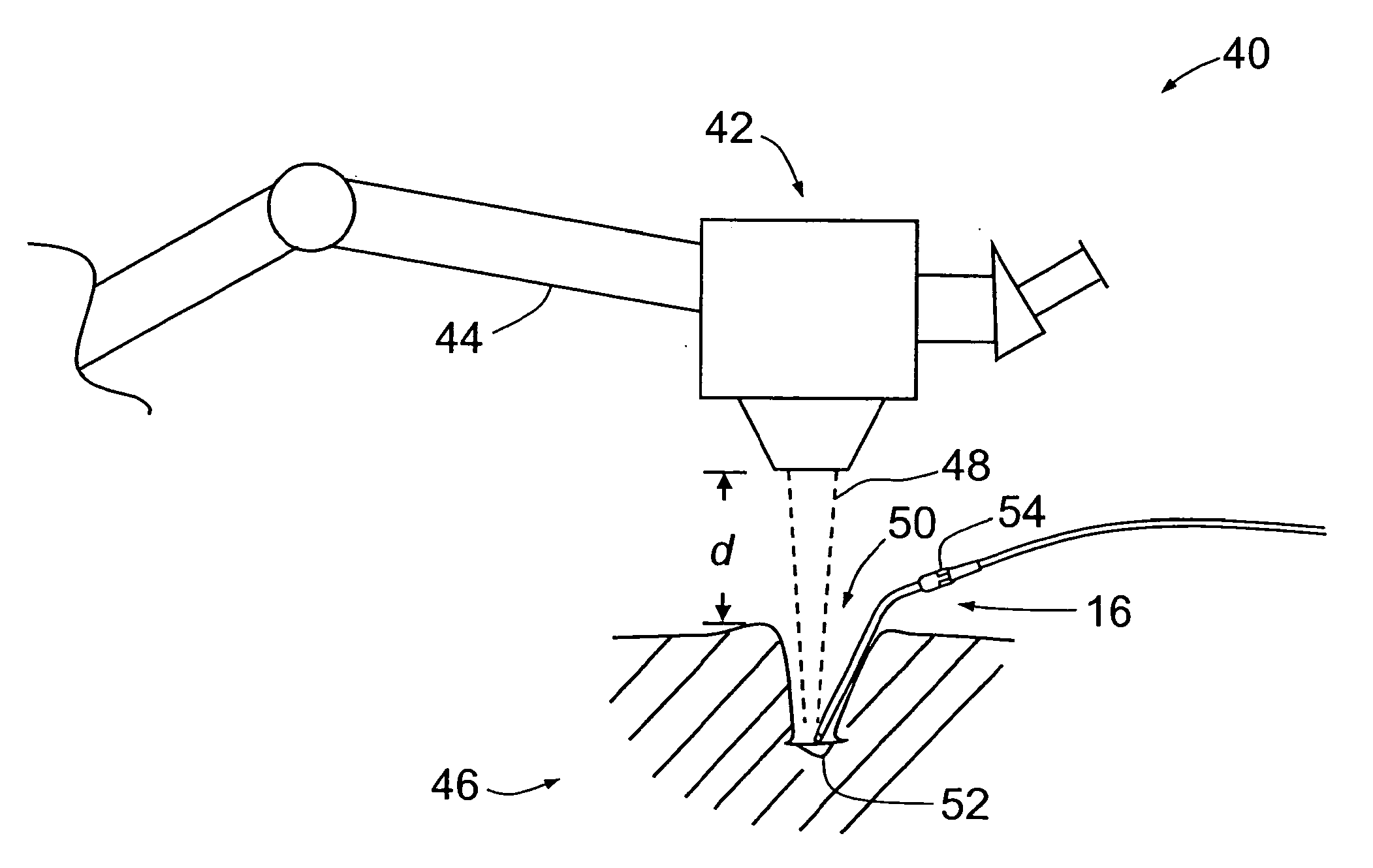
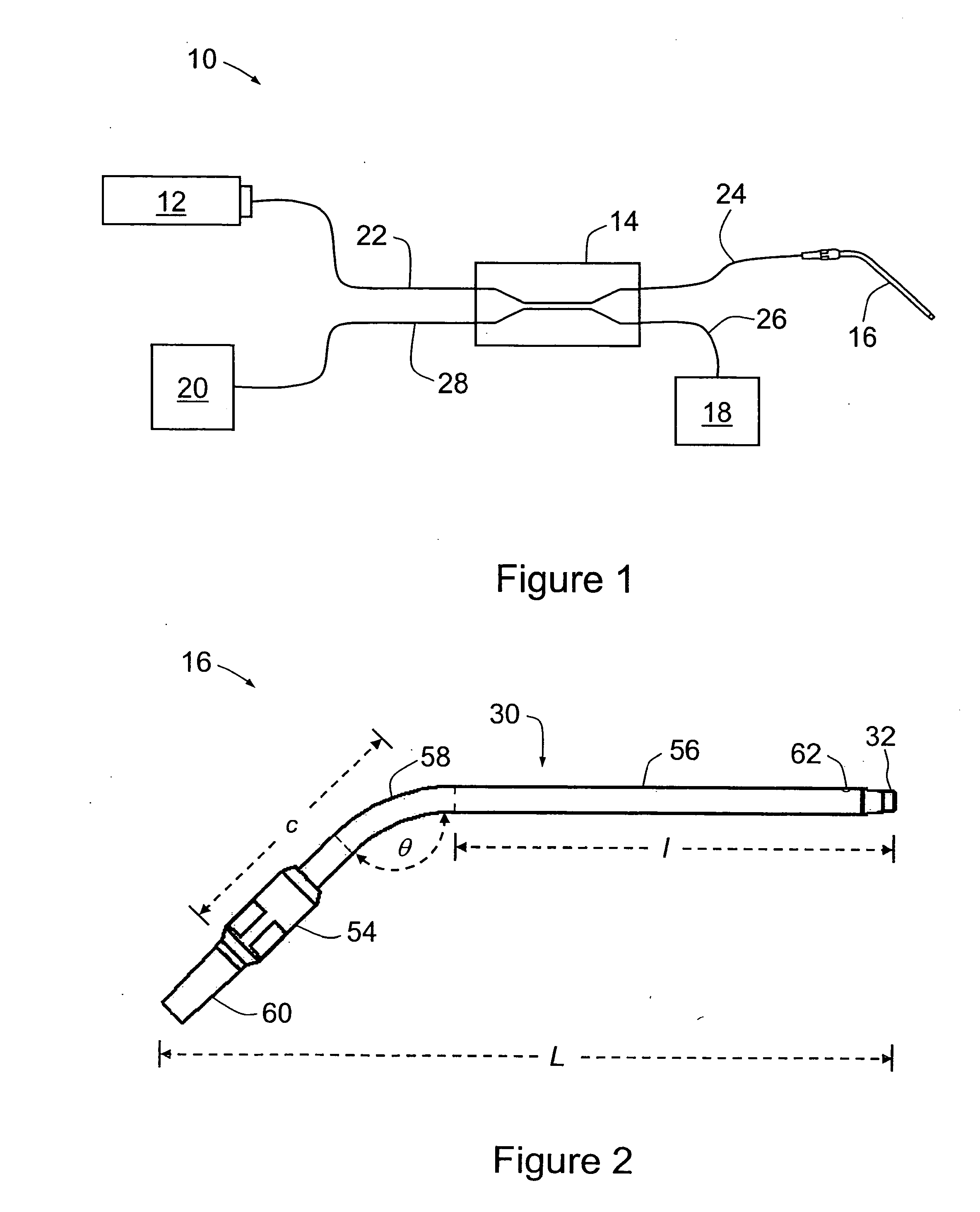
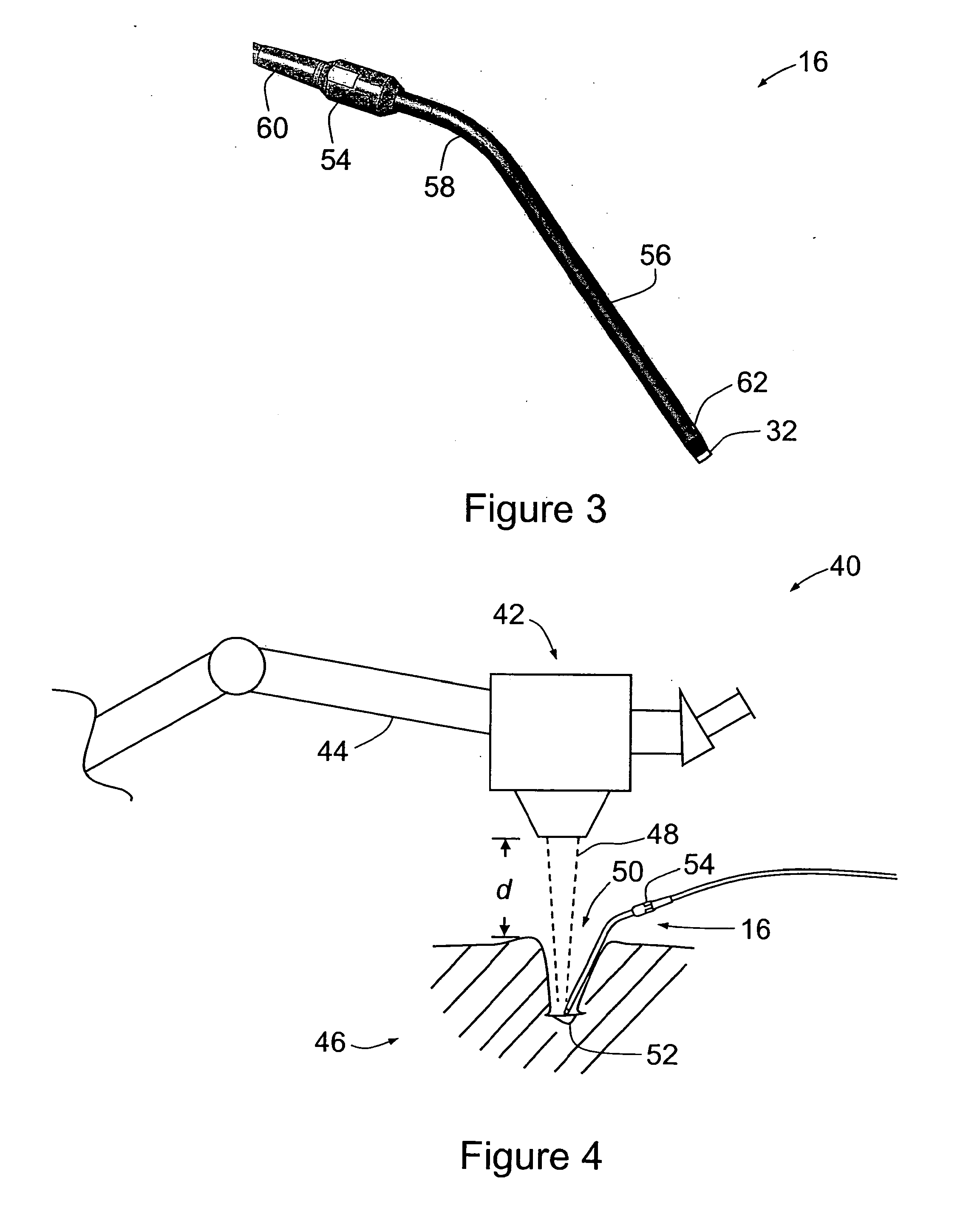
[0014]FIG. 1 is a schematic view of an endomicroscope system 10 according to an embodiment of the present invention. System 10 includes a laser source 12 with 488 nm wavelength output, a light separator in the form of an optical coupler 14, a confocal endomicroscope probe 16, a power monitor 18 and a detection unit 20. System 10 includes a control box (not shown) that houses laser source 12 and detection unit 20 (in the form of a photomultiplier tube), and a computer (not shown) for receiving, storing and displaying data from detection unit 20. Probe 16 includes an x-y scanning mechanism (not shown) so that light emitted by probe 16 has a point observational field that is scanned in a raster scan so that an image of the observational field—comprising a portion of a sample—can be collected and displayed. System 10 therefore also includes electrical cables for transmitting a scanning signal from the aforementioned control box to probe 16, for powering the scanning mechanism.

[0015]In u...


PUM


Abstract

An imaging apparatus and method are provided. The probe for an imaging apparatus includes a manually manipulable proximal portion; a straight distal portion with a distal tip for locating at a site to define an observational field; and a curved portion between the proximal portion and the distal portion. The imaging method includes the steps of locating a distal tip of an imaging probe at a site to define an observational field; irradiating the observational field from the distal tip; and collecting a return signal at the distal tip; wherein the probe comprises a manually manipulable proximal portion. The apparatus and method provided herein are useful for various applications including but not limited to endomicroscopy and other microsurgical procedures performed under optical stereoscopic magnified visualization, such as neurosurgery, ENT/facial surgery and spinal surgery.

Description

CROSS REFERENCE TO RELATED APPLICATIONS[0001]This application claims the benefit of U.S. Provisional Patent Application No. 61 / 212,272 filed Apr. 8, 2009, the entire contents of which is hereby incorporated herein by reference.FIELD OF THE INVENTION[0002]The present invention relates generally to an imaging method and apparatus, of particular but by no means exclusive application in endomicroscopy and in microsurgical and other procedures performed under optical stereoscopic magnified visualization, including neurosurgery, ENT / facial surgery and spinal surgery.BACKGROUND OF THE INVENTION[0003]One existing microscopic probe comprises an endoscope or endomicroscope, with an endoscopic head for insertion into a patient (through the mouth or anus) coupled to a laser source by an optical fibre or optical fibre bundle. Another microscopic probe is similar to this endoscope, but adapted for examining the skin.SUMMARY OF THE INVENTION[0004]According to a first aspect of the invention, there...

Claims


Application Information

Patent Timeline
Patent Type & Authority Applications(United States)
IPC IPC(8): A61B1/06
CPCA61B1/00041A61B1/267A61B1/0008A61B1/00172A61B1/042A61B1/313A61B5/0068A61B5/0084A61B5/064A61B5/065A61B5/6835A61B5/6852A61B5/6855G02B21/0028G02B23/2476A61B2019/444A61B19/44A61B8/12A61B5/0075A61B5/0066A61B2019/446A61B1/233A61B1/227A61B1/06A61B1/00078A61B1/00009A61B1/0005A61B90/90A61B90/92A61B90/94A61B1/0004A61B7/02A61B1/00045
Inventor MIESNER, HANS-JOACHIMHAUGER, CHRISTOPHNAHM, WERNERRUDOLPH, FRANKHATTENDORF, GUIDODELANEY, PETER MAXWELLALLEN, JOHN D.
Owner CARL ZEISS MEDITEC INC
Why Eureka
Try Eureka