Transparent thermally conductive polymer composites for light source thermal management

a technology of thermal management and transparent thermal conductive polymer, which is applied in the direction of discharge tube luminescnet screens, semiconductor devices for light sources, lighting and heating apparatus, etc., can solve the problems of poor color quality, acquisition cost, and warm-up tim

a technology of thermal management and transparent thermal conductive polymer, which is applied in the direction of discharge tube luminescnet screens, semiconductor devices for light sources, lighting and heating apparatus, etc., can solve the problems of poor color quality, acquisition cost, and warm-up tim

US20110169394A1Active Publication Date: 2011-07-14CONSUMER LIGHTING (U S) LLC

Image

  • Transparent thermally conductive polymer composites for light source thermal management
  • Transparent thermally conductive polymer composites for light source thermal management
  • Transparent thermally conductive polymer composites for light source thermal management

Examples


Embodiment Construction

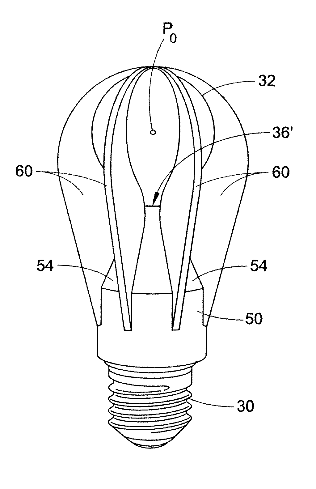
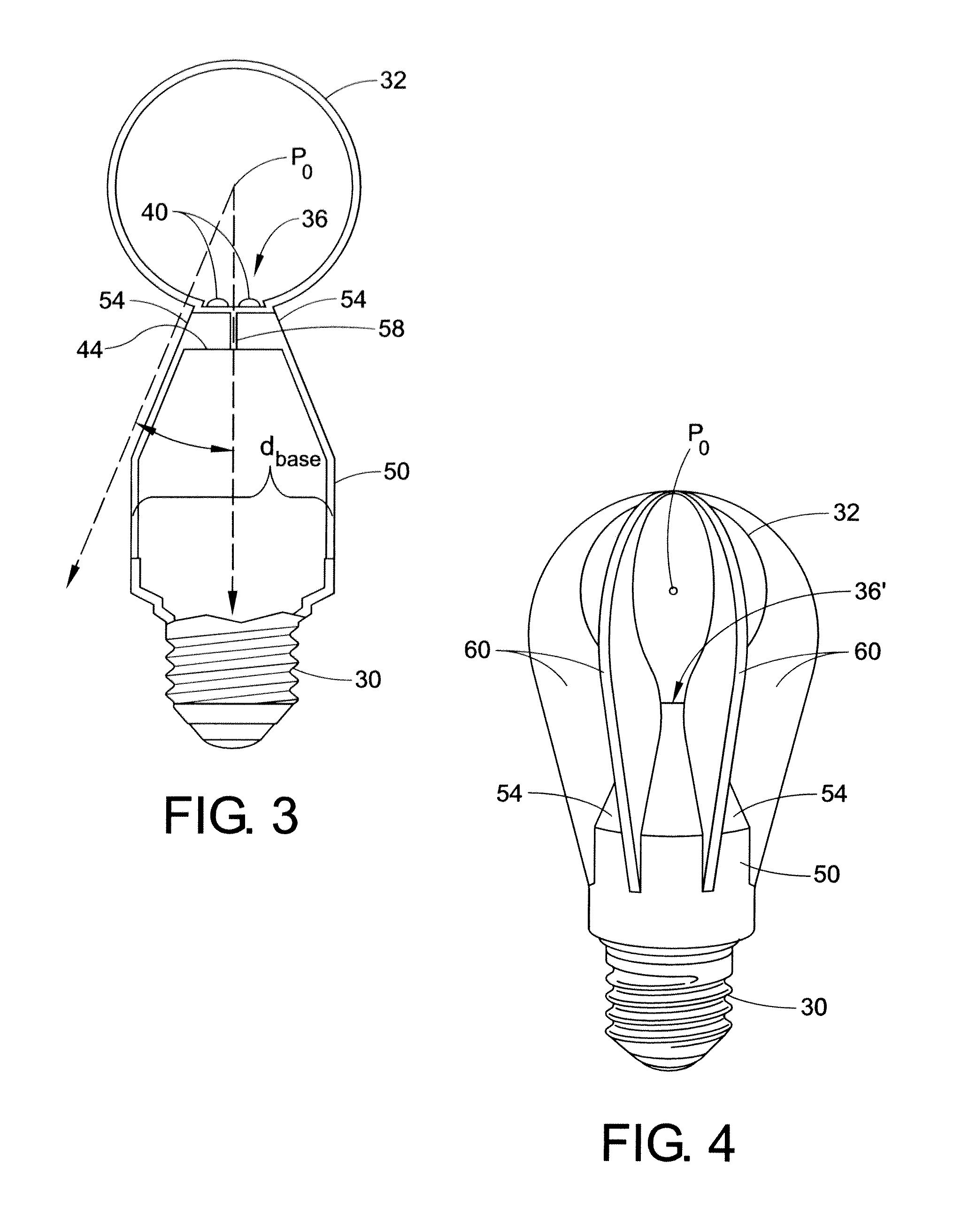
[0031]The present disclosure is directed to solving the weight, size and cost problems of thermal management in LED and OLED lamps and lighting systems, while simultaneously avoiding light blockage, by providing the relatively high thermal conductivity of heretofore optically opaque polymers in an optically transmissive polymer, and incorporating the design of the optically transmissive polymer into the LED or OLED lamp or lighting system. This solution utalizes polymer composites filled with a relatively low density of high thermal conductivity carbon nanotubes such that the thermal conductivity of the composite polymer is comparable to that of aluminum, while the optical transmission is comparable to that of clear glass, so that the composite polymer may be used as heat fins and thermally conductive optical elements.

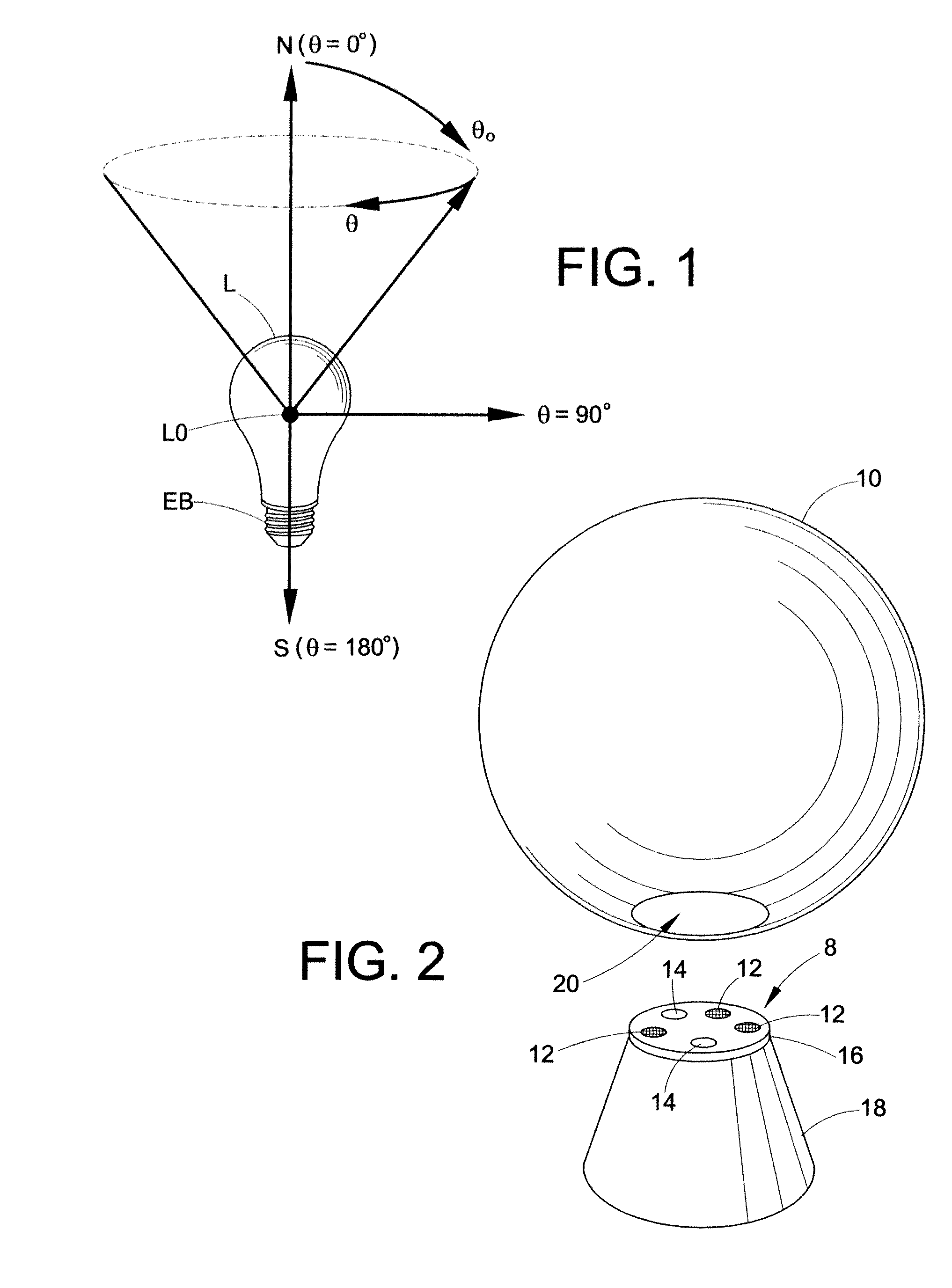
[0032]With reference to FIG. 2, an LED based lamp includes a planar LED-based Lambertian light source 8 and a light-transmissive spherical envelope 10 in a configurati...


PUM


Abstract

A light emitting apparatus is provided. The light emitting apparatus includes a light transmissive envelope, a light source being in thermal communication with a heat sink, and a plurality of heat fins in thermal communication with the heat sink and extending in a direction such that the heat tins are adjacent the light transmissive envelope. The plurality of heat fins comprises a carbon nanotube filled polymer composite.

Description

[0001]This application claims the benefit of U.S. Provisional Application No. 61 / 294,231 filed Jan. 12, 2010. U.S. Provisional Application No. 61 / 294,231 filed Jan. 12, 2010 is incorporated herein by reference in its entirety.BACKGROUND[0002]The present exemplary embodiment relates to illumination devices, and particularly to illumination devices including light emitting diodes (LED). However, it is to be appreciated that the present exemplary embodiment is also amenable to other like applications.BRIEF DESCRIPTION[0003]Incandescent and halogen lamps are conventionally used as omni-directional, non-directional and directional light sources, especially in residential, hospitality, and retail lighting applications. Omni-directional lamps are intended to provide substantially uniform intensity distribution versus angle in the far field, greater than 1 meter away from the lamp, and find diverse applications such as in desk lamps, table lamps, decorative lamps, chandeliers, ceiling fixtu...

Claims


Application Information

Patent Timeline
14 Jul 2011
Publication
US20110169394A1
IPC
H01J61/52; H01J1/62
CPC
F21K9/135; F21V29/004; F21Y2101/02; F21V29/87; F21V29/506; F21V29/77; F21V3/02; F21K9/232
Inventors
CHOWDHURY, ASHFAQUL ISLAM; ALLEN, GARY