Permanent Magnet Arrangement for an Electrical Machine
a permanent magnet and electrical machine technology, applied in the direction of magnets, magnet bodies, propulsion systems, etc., can solve the problems of prone to fracture and corrosion, brittle permanent magnet material from which the magnet pole is formed, etc., and achieve the effect of assisting with the control of electrical stability
- Summary
- Abstract
- Description
- Claims
- Application Information
AI Technical Summary
Benefits of technology
Problems solved by technology
Method used
Image
Examples
first embodiment
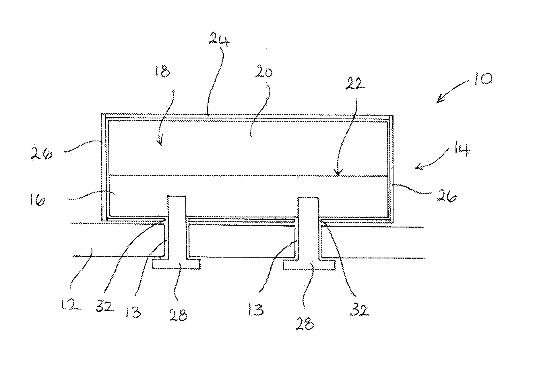
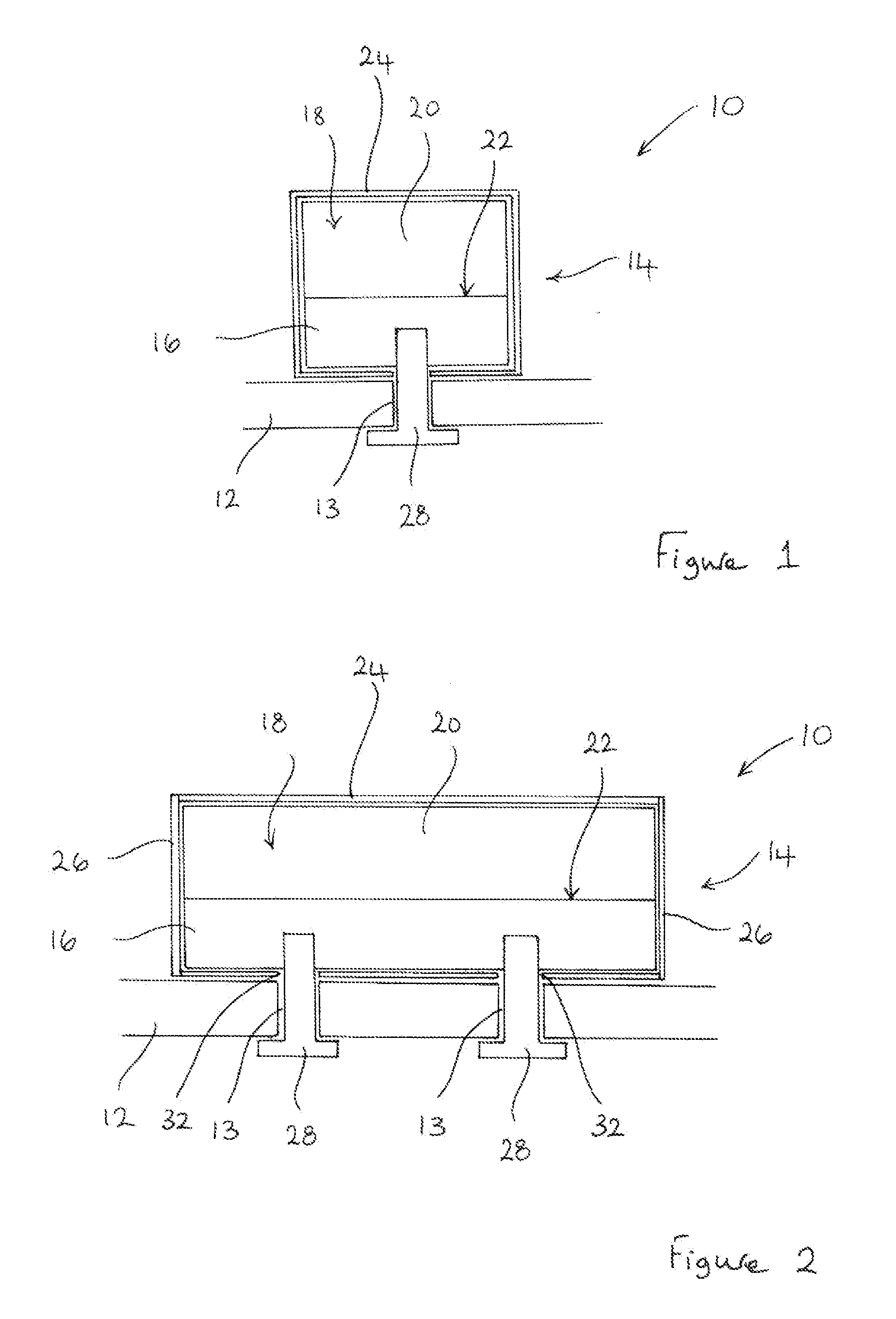
[0042]Referring initially to FIGS. 1 and 2, a permanent magnet arrangement 10 for an electrical machine comprises a support structure 12 including a plurality of apertures 13 and a pole assembly 14 fixed to the support structure 12. The support structure 12 is capable of carrying magnetic flux and is typically the rotor of an electrical machine. The rotor may be a cylindrical rotor of a radial flux machine, a disc rotor of an axial flux machine or a linear rotor (i.e. a translator) of a linear machine.
[0043]The pole assembly 14 comprises a generally elongate magnet carrier 16 made of magnetic material, such as steel, and a magnet pole 18 comprising one or more pieces of permanent magnet material 20. The magnet pole 18 is bonded to a surface 22 of the magnet carrier 16 but, as indicated above, the magnet pole 18 may be secured to the surface 22 of the magnet carrier 16 by any suitable means.
[0044]The permanent magnet arrangement 10 comprises a protective sleeve 24 into which the pole...
second embodiment
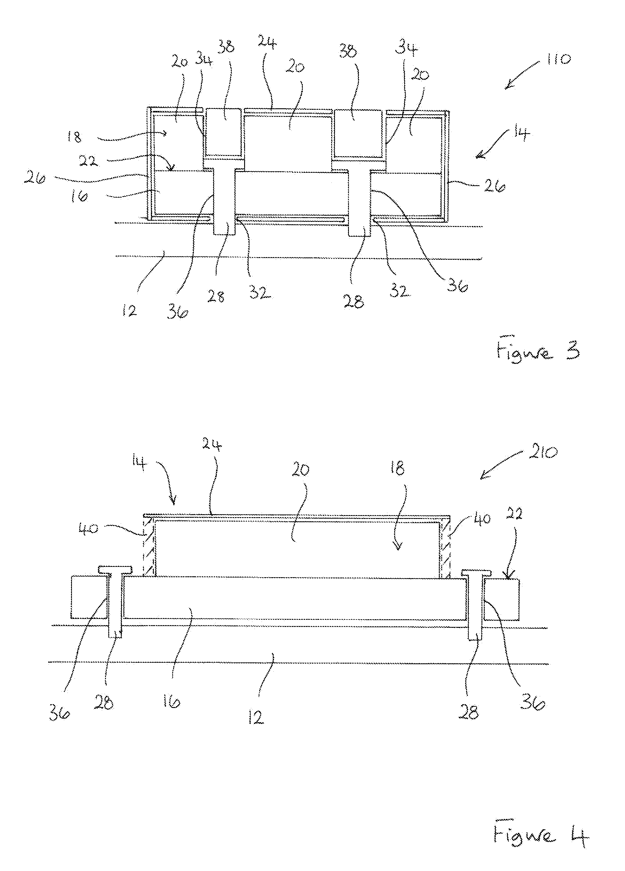
[0049]FIG. 3 illustrates a permanent magnet arrangement 110 which is similar to the permanent magnet arrangement illustrated in FIGS. 1 and 2 and in which corresponding features are designated using corresponding reference numerals.
[0050]In the permanent magnet arrangement 110, the pole assembly 14 comprises a plurality of pieces of permanent magnet material 20 secured to the surface 22 of the magnet carrier 16. The individual pieces of permanent magnet material 20 are spaced apart to define openings 34 for receiving the mechanical fixings 28. The mechanical fixings 28 extend though apertures 36, 32 in both the magnet carrier 16 and the protective sleeve 24 to enable the mechanical fixings 28 to engage the support structure 12. The mechanical fixings 28 thus cooperate with both the magnet carrier 16 and the support structure 12 so that they fix the magnet carrier 16, and hence the pole assembly 14, to the support structure 12. The protective sleeve 24 is again clamped to the support...
third embodiment
[0053]FIG. 4 illustrates a permanent magnet arrangement 210 which is generally similar to the permanent magnet arrangement illustrated in FIGS. 1 and 2 and in which corresponding features are designated using corresponding reference numerals.
[0054]In the permanent magnet arrangement 210, the magnet pole 18 is fully contained within the protective sleeve 24 to provide it with the necessary mechanical and environmental protection. However, the ends of the magnet carrier 16 extend from the ends of the protective sleeve 24 and are, thus, exposed. It is those exposed ends of the magnet carrier 16 that are secured to the support structure 12 by the mechanical fixings 28.
[0055]In this particular embodiment, the use of end caps 26 to close the ends of the protective sleeve 24 may be inappropriate. Closure means in the form of sealant material 40 may instead be used to close the ends of the protective sleeve 24 to maximise the mechanical and environmental protection provided to the magnet po...
PUM
 Abstract
Description
Claims
Application Information
 - R&D
- Intellectual Property
- Life Sciences
- Materials
- Tech Scout
- Unparalleled Data Quality
- Higher Quality Content
- 60% Fewer Hallucinations
Browse by: Latest US Patents, China's latest patents, Technical Efficacy Thesaurus, Application Domain, Technology Topic, Popular Technical Reports.
© 2025 PatSnap. All rights reserved.Legal|Privacy policy|Modern Slavery Act Transparency Statement|Sitemap|About US| Contact US: help@patsnap.com


