Solid oxide fuel cell apparatus

a fuel cell and solid oxide technology, applied in the field of solid oxide fuel cell apparatuses, can solve the problems of warpage of fuel cells, damage to the anode of fuel cells, and impaired electrical contact between fuel cells and current collectors, so as to achieve the effect of maintaining the follow-up deformation of the cell-follow-up deformation member more effectively

Active Publication Date: 2011-07-14
MORIMURA SOFC TECH CO LTD
View PDF7 Cites 27 Cited by
  • Summary
  • Abstract
  • Description
  • Claims
  • Application Information

AI Technical Summary

Benefits of technology

[0057]In the case where the spacer member is formed of foam metal, in order to mitigate the condition in which the foam metal and the first or second metal plate seize in relation to each other, the foam metal may have an electrically insulative material provided on its surface in contact with the first metal plate and an electrically insulative material pr

Problems solved by technology

Meanwhile, a thermal cycle which the solid oxide fuel cell apparatus is subjected to in the course of operation or the like causes warpage to the fuel cells.
Specifically, because of a poor match in thermal expansion coefficient between an

Method used


Image

  • Solid oxide fuel cell apparatus
  • Solid oxide fuel cell apparatus
  • Solid oxide fuel cell apparatus

Examples


first embodiment

[0093]An embodiment of the present invention will next be described with reference to the drawings.

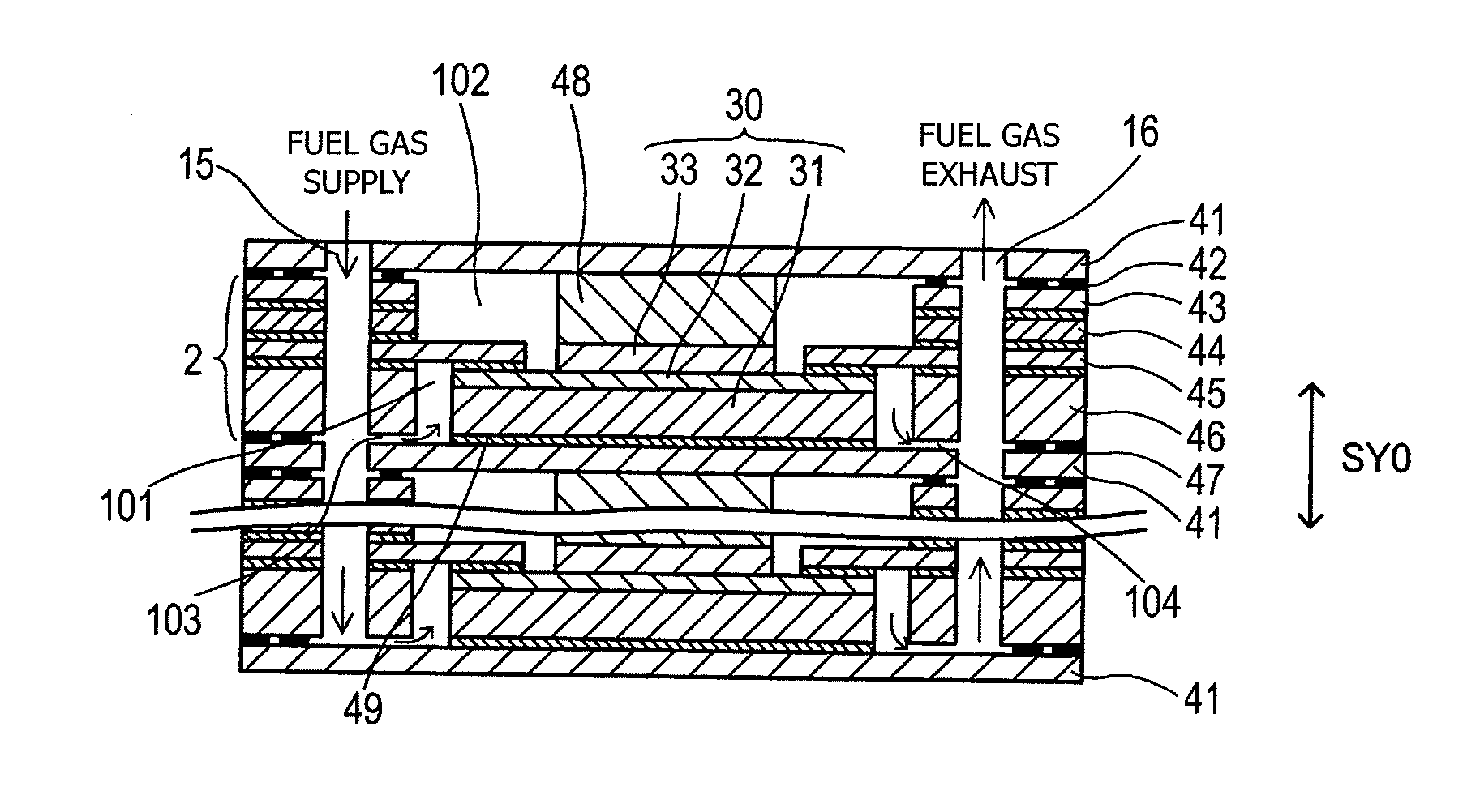
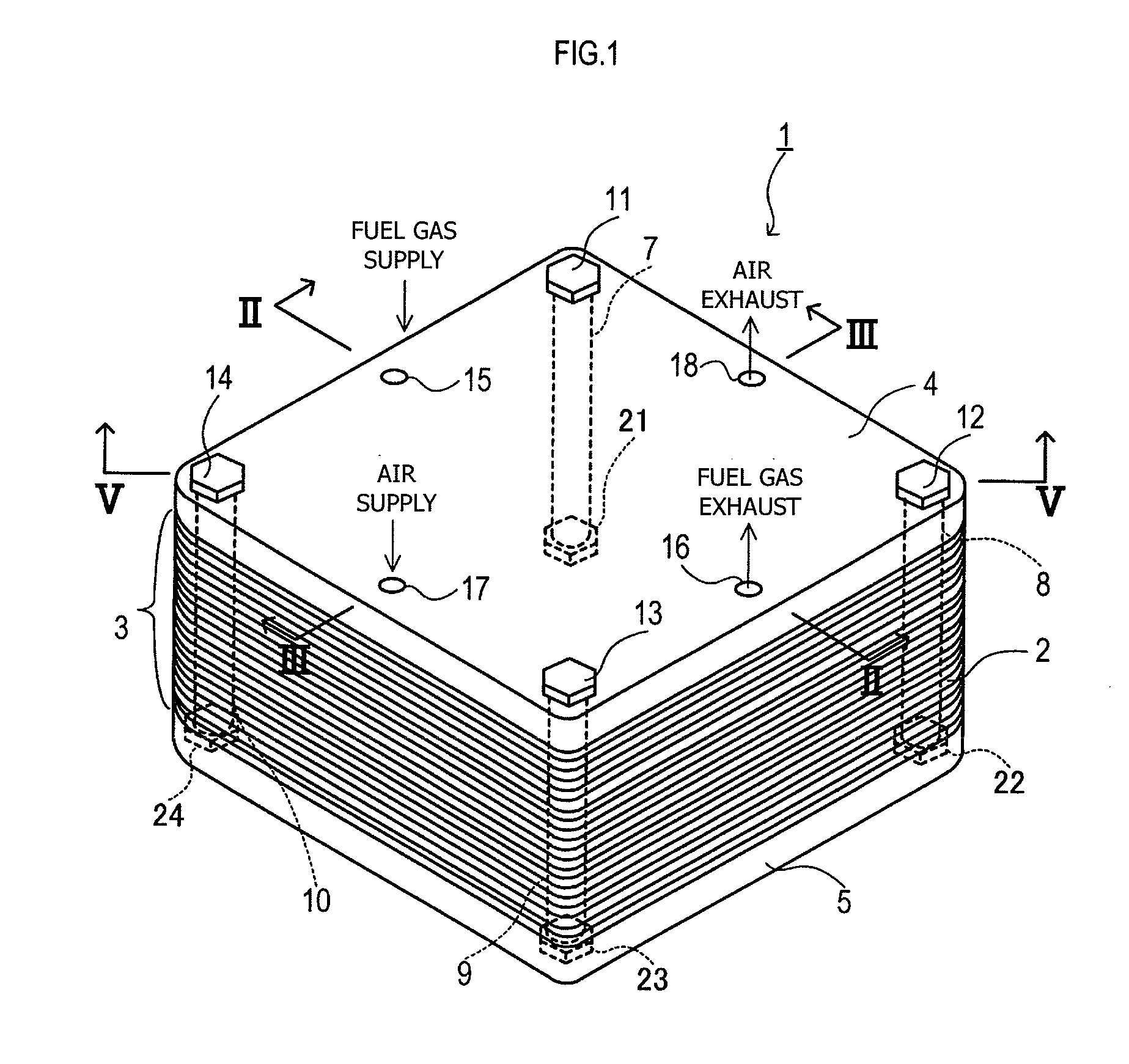
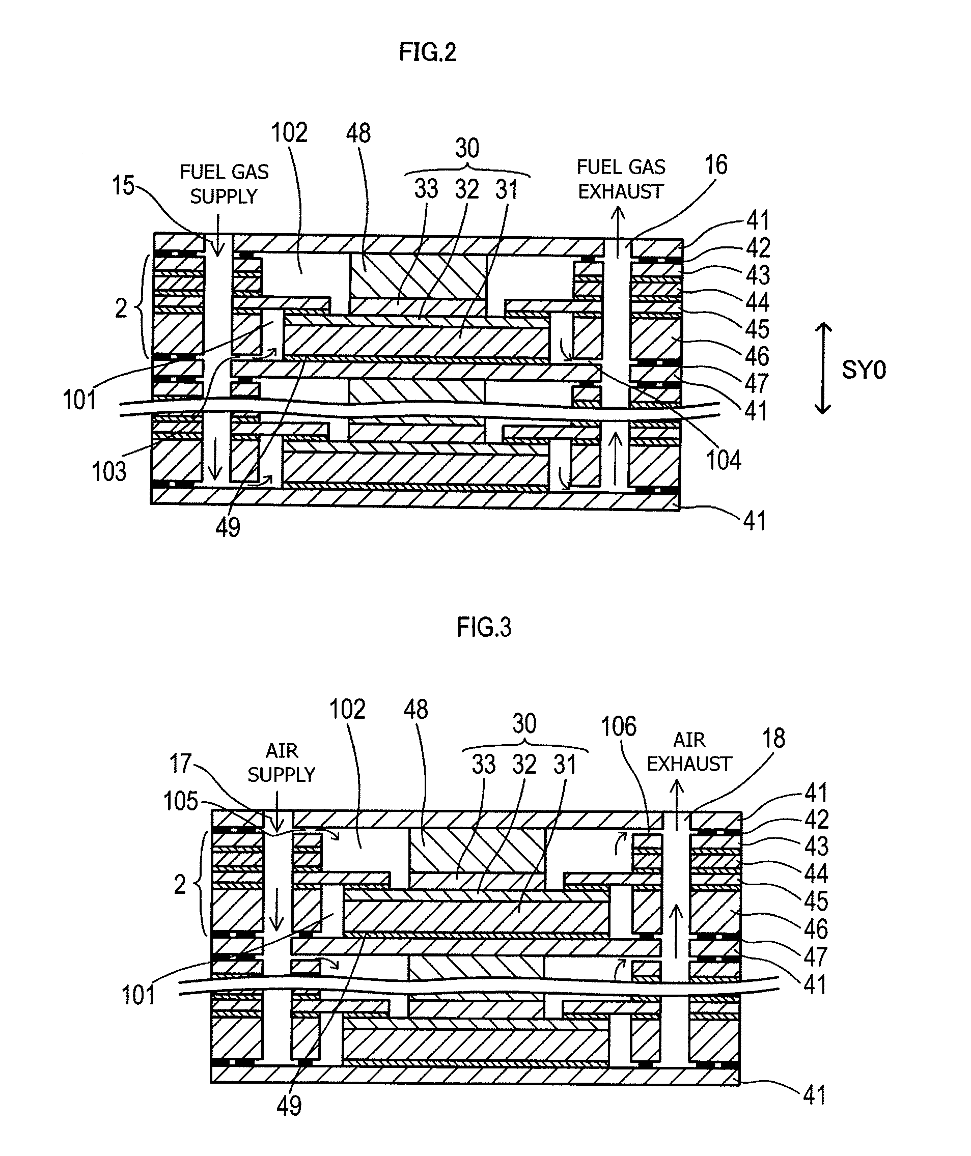
[0094]FIG. 1 is a perspective view of a solid oxide fuel cell apparatus 1 to which the present invention is applied; FIG. 2 is a schematic sectional view of a fuel cell stack 3 taken along line II-II of FIG. 1; FIG. 3 is a schematic sectional view of the fuel cell stack 3 taken along line III-III of FIG. 1; FIG. 4 is an exploded perspective view showing the solid oxide fuel cell apparatus 1; FIG. 5 is a schematic sectional view taken along line V-V of FIG. 1; and FIGS. 6A-6C are exploded plan views showing an end holder member (a cell-follow-up deformation member composed of an electricity-nongenerating laminate and a plate-shaped electrically conductive member) 4, 5.

[0095]As shown in FIG. 1, the solid oxide fuel cell apparatus (hereinafter, referred to merely as the fuel cell apparatus) 1 is adapted to generate electricity with fuel gas (e.g., hydrogen) and oxidizer gas (e.g., air (sp...

second embodiment

[0141]A second embodiment of the present invention will next be described with reference to the drawings. The description of the second embodiment covers only those features different from those of the first embodiment. FIG. 8 is a schematic sectional view of the fuel cell apparatus 1 of the second embodiment.

[0142]As shown in FIG. 8, the solid oxide fuel cell apparatus 1 of the second embodiment is similar to that of the first embodiment, except that the laminate 70 of the end holder member 4 is disposed such that the different-thermal-expansion member 72 is in contact with the upper frame 83. That is, the end holder member 4 and the end holder member 5 have the same laminate stacking orientation SY3.

[0143]In the thus-configured fuel cell apparatus 1, the laminate stacking orientation SY3 of the end holder members 4, 5 and a direction SY4 from the anode 31 toward the solid electrolyte 32 in the cell 30 (hereinafter, referred to as the cell stacking orientation SY4) can be the same....

third embodiment

[0147]A third embodiment of the present invention will next be described with reference to the drawings. The description of the third embodiment covers only those features different from those of the first embodiment. FIG. 9 is a schematic sectional view of the fuel cell apparatus 1 of the third embodiment.

[0148]As shown in FIG. 9, the solid oxide fuel cell apparatus 1 of the third embodiment is similar to that of the first embodiment, except that the fuel cell apparatus 1 includes a plurality of fuel cell stacks 3, 3′, and the end holder member 4 or the end holder member 5 is also disposed between the fuel cell stack 3 and the fuel cell stack 3′.

[0149]According to the present embodiment, the end holder member is disposed between the fuel cell stack and the fuel cell stack. However, the end holder member may be disposed between the fuel cell and the fuel cell within the fuel cell stack. In this case, each of the upper and lower frames used to hold the laminate 70 therebetween is for...


PUM


Abstract

[Means for Solution] A solid oxide fuel cell apparatus including a fuel cell having a plate-shaped first solid electrolyte, an anode provided on one side of the first solid electrolyte and coming in contact with fuel gas, and a cathode provided on the other side of the first solid electrolyte and coming in contact with oxidizer gas. The solid oxide fuel cell apparatus further includes a cell-follow-up deformation member located on at least one of opposite sides of the fuel cell with respect to a first stacking direction along which the anode, the first solid electrolyte, and the cathode are stacked together. The cell-follow-up deformation member deforms according to a deformation of the fuel cell on the basis of at least one of physical quantities including differential thermal expansion coefficient and differential pressure.

Description

TECHNICAL FIELD[0001]The present invention relates to a solid oxide fuel cell apparatus (battery) which includes fuel cells each having an anode, a cathode, and a solid electrolyte.BACKGROUND ART[0002]Conventionally known fuel cell apparatus include a solid oxide fuel cell apparatus using solid electrolyte (solid oxide). The solid oxide fuel cell apparatus includes a fuel cell stack in which a large number of fuel cells are stacked together. Each of the fuel cells is configured, for example, such that a cathode and an anode are provided on respective opposite sides of a plate-shaped solid electrolyte. Air is supplied to the cathode, and fuel gas is supplied to the anode, whereby the fuel gas and oxygen contained in air react chemically with each other via the solid electrolyte, thereby generating electricity. The solid oxide fuel cell apparatus also includes current collectors which are in contact with respective anode and cathode electrically for establishing electrical communicati...

Claims


Application Information

Patent Timeline
IPC IPC(8): H01M8/24H01M8/10
CPCH01M8/12Y02E60/521Y02E60/525H01M2008/1293H01M8/248H01M8/006H01M8/2425H01M8/2432H01M8/2483Y02E60/50H01M8/0273
Inventor HAYASHI, CHIEISHIKAWA, HIROYAFURUSAKI, KEIZOOKUYAMA, YASUOTODO, YUSUKEKOMATSU, DAISUKE
Owner MORIMURA SOFC TECH CO LTD
Why Eureka
Try Eureka