Distributed doherty power amplifier

a technology of power amplifier and doherty, which is applied in the direction of amplifiers, amplifiers with coupling networks, amplifiers with semiconductor devices/discharge tubes, etc., can solve the problems of difficult to acquire high efficiency in a conventional doherty power amplifier, and difficult to operate a doherty power amplifier at the other frequencies, so as to prevent leakage

Inactive Publication Date: 2011-07-21
POSTECH ACAD IND FOUND
View PDF3 Cites 38 Cited by
  • Summary
  • Abstract
  • Description
  • Claims
  • Application Information

AI Technical Summary

Benefits of technology

[0018]Furthermore, the Doherty power amplifier includes a distributor, which divides an input of the Doherty power amplifier into two signals and inputs the two signals to the carrier amplifier and the peaking amplifier, respectively; a second transmission line, which is connected to the output of the peaking amplifier and prevents leakage of the output of the carrier amplifier; a second transmission line, which is connected to the output of the carrier amplifier and compensates for a delay of the first transmission line; and a third transmission line, which is connected to the output of the first transmission line and the output of the second transmission line and adjusts load impedance of the carrier amplifier.

Problems solved by technology

As described above, in a conventional Doherty power amplifier, although a λ / 4 transmission line plays a major role for changing an output impedance, a λ / 4 transmission line designed to be bound to a single operation frequency cannot function as a λ / 4 transmission line at other frequencies, and thus it is difficult to operate a Doherty power amplifier at the other frequencies.
Therefore, it is difficult to acquire high efficiency in a conventional Doherty power amplifier.
Furthermore, although a conventional distributed power amplifier has an advantage in terms of a broad bandwidth, the conventional distributed power amplifier is mostly used as a gain amplifier or a drive amplifier used at a low output due to small output power and low efficiency.

Method used


Image

  • Distributed doherty power amplifier
  • Distributed doherty power amplifier
  • Distributed doherty power amplifier

Examples


Embodiment Construction

[0031]The present invention will now be described more fully with reference to the accompanying drawings, in which exemplary embodiments of the invention are shown. In the description of the present invention, if it is determined that a detailed description of commonly-used technologies or structures related to the invention may unnecessarily obscure the subject matter of the invention, the detailed description will be omitted. Also, since later-described terms are defined in consideration of the functions of the present invention, they may vary according to users' intentions or practice. Hence, the terms must be interpreted based on the contents of the entire specification.

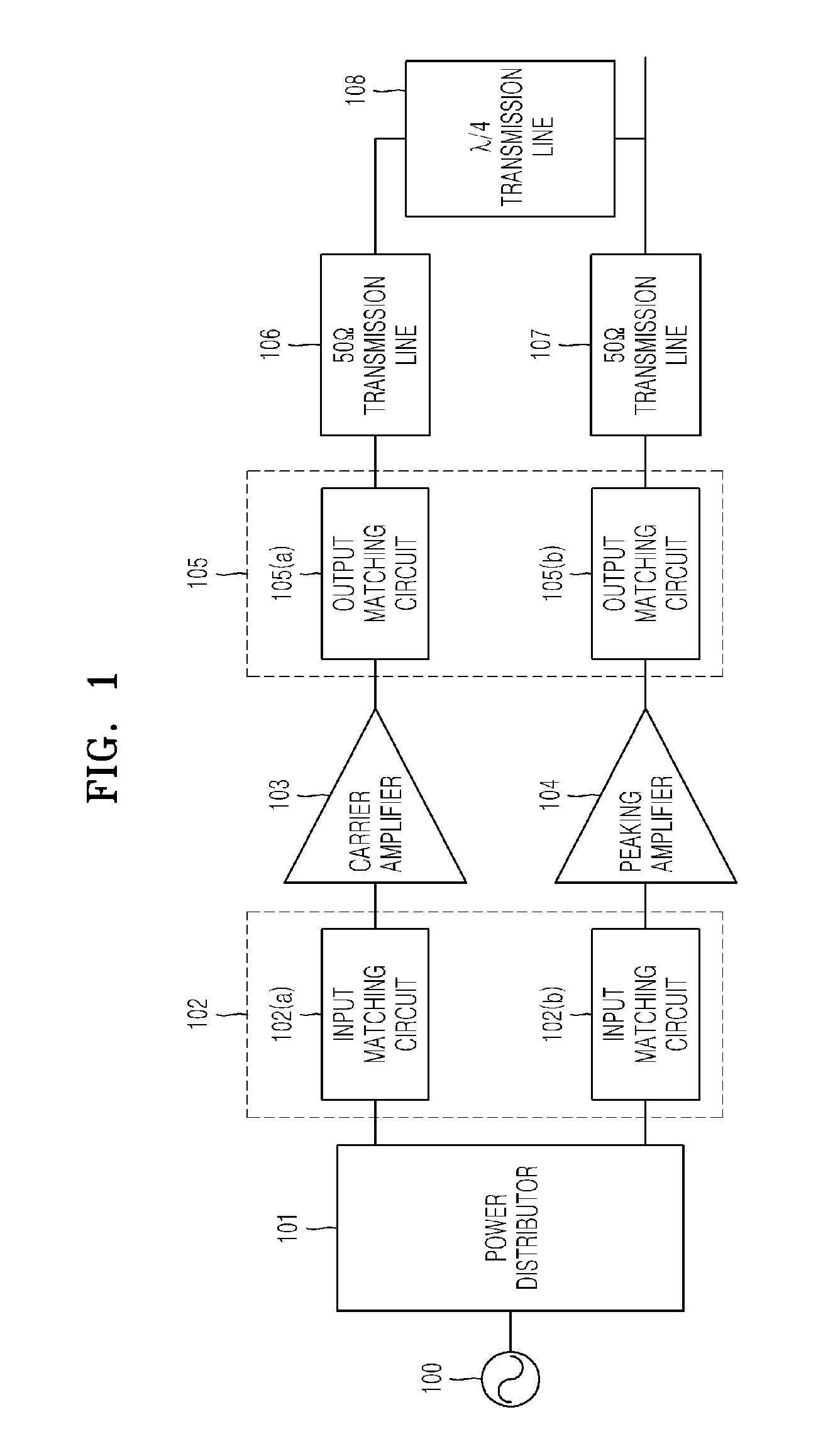
[0032]FIG. 1 is a circuit diagram of a Doherty power amplifier.

[0033]Referring to FIG. 1, a source signal generated by a signal generator 100 is divided into two signals, of which phases are different by 90°, via a power distributor 101. A Doherty power amplifier has a structure in which a carrier amplifier 103 a...


PUM


Abstract

Provided is a distributed Doherty power amplifier exhibiting high efficiency and linearity at a wide range of bandwidths, the distributed Doherty power amplifier including a first amplifier; a second amplifier, which is connected to the first amplifier in parallel; a first shifting unit, which is interconnected between the input of the first amplifier and the input of the second amplifier and inverses the phase of the input of the second amplifier; and a second shifting unit, which is interconnected between the output of the first amplifier and the output of the second amplifier and inverses the phase of the output of the second amplifier, wherein the first amplifier and the second amplifier are Doherty power amplifiers, and each of the Doherty power amplifiers includes a carrier amplifier and a peaking amplifier, which are connected in parallel.

Description

[0001]CROSS-REFERENCE TO RELATED PATENT APPLICATION[0002]This application claims the benefit of Korean Patent Application No. 10-2010-0005078, filed on Jan. 10, 2010, in the Korean Intellectual Property Office, the disclosure of which is incorporated herein in its entirety by reference.BACKGROUND OF THE INVENTION[0003]1. Field of the Invention[0004]The present invention relates to a distributed Doherty power amplifier, and more particularly, to a power amplifier, which exhibits broadband characteristics by connecting a first Doherty power amplifier and a second Doherty power amplifier in a distributed structure and exhibits a characteristic of offsetting tertiary distortion signals generated from the first Doherty power amplifier and the second Doherty power amplifier.[0005]2. Description of the Related Art[0006]Currently, a mobile communication system requires broad bandwidth and high linearity. Signals having broad bandwidth and high linearity exhibit a high peak-to-average power ...

Claims


Application Information

Patent Timeline
Patent Type & Authority Applications(United States)
IPC IPC(8): H03F1/07
CPCH03F1/0288H03F3/195H03F3/211H03F3/24H03F3/602H03F2203/21142H03F2200/387H03F2200/423H03F2200/543H03F2203/21106H03F2200/222
Inventor JEONG, YOON-HALEE, MUN-WOOLEE, YONG-SUB
Owner POSTECH ACAD IND FOUND
Why Eureka
Try Eureka