Fiber assembly, composite of electro conductive substrate and fiber assembly, and production methods thereof

a technology of electro conductive substrate and fiber assembly, which is applied in the direction of sustainable manufacturing/processing, cell components, melting methods, etc., can solve the problems of affecting the production efficiency of the product, affecting the quality of the product, so as to achieve the effect of reducing the cost of production

Inactive Publication Date: 2011-07-21
DAIWABO HLDG +1
View PDF14 Cites 44 Cited by
  • Summary
  • Abstract
  • Description
  • Claims
  • Application Information

AI Technical Summary

Benefits of technology

[0020]According to the present invention, it is possible to obtain a fiber assembly by forming a composite-resin-formed product containing a combination of a component on which it is difficult to perform electrospinning and a component having a volume specific resistance less than or equal to a specific value into an ultrafine composite fiber by electrospinning without the use of any solvent or water as a spinning solution, and accumulating the ultrafine composite fiber. In addition, the component on which it is difficult to perform electrospinning, serving as a sea component and / or sheath component, is used as a thermally adhesive component to thermally bond portions of the ultrafine composite fiber, and it is therefore possible to obtain a fiber assembly having a high tensile strength and puncture strength, such as a thermally-bonded non-woven fabric. Even when the fiber assembly of the present invention is heat-treated, the composite fiber does not form a film and maintains its fibrous form. The fiber assembly of the present invention undergoes less thermal shrinkage than commonly used non-woven fabrics.
[0021]A composite of an electro conductive substrate and a fiber assembly according to the present invention is produced by electrospinning a composite-resin-formed product containing a combination of a component on which it is difficult to perform electrospinning and a component having a volume specific resistance less than or equal to a specific value into an ultrafine composite fiber, and covering and integrating at least a part or all of the surface of an electro conductive substrate with a fiber assembly made of the ultrafine composite fiber, so that the composite provides ease of handling and improved work efficiency when, for example, housing it in a battery.

Problems solved by technology

This method, however, is disadvantageous in that it requires removal of a large amount of sea component by using a solvent after spinning or production of the non-woven fabric, which makes the process complex and costly.
Merely laminating (without fixing) the electrode plates and the separator is problematic in that, since the separator itself is thin, the electrode plates and the separator may be displaced relative to each other or wrinkled during the process of housing them in a battery.
In addition, in order to reduce such displacement and wrinkling, it is necessary to set the line tension during the housing process so as to correspond to the separator having a low tensile strength, and this causes a problem of slowing down the production.
That is, there is a process of affixing the electrode plate and the separator, and inhibition of displacement and wrinkling has not been achieved.
Recently, attempts have been made to produce a battery separator by using a solution electrospinning method (Patent Document 6), but this technique is employed only to process a single component polymer into a fiber to give a separator, and such separators have a problem of undergoing significant shrinkage during heat treatment.
Also, there is another problem: in the solution electrospinning method, in particular, the solvent or water used during the spinning process remains in the fiber, which may have harmful effects on the product.

Method used


Image

  • Fiber assembly, composite of electro conductive substrate and fiber assembly, and production methods thereof
  • Fiber assembly, composite of electro conductive substrate and fiber assembly, and production methods thereof
  • Fiber assembly, composite of electro conductive substrate and fiber assembly, and production methods thereof

Examples


examples

[0099]Hereinafter, the present invention will be described in further detail by way of examples. It should be noted that the present invention is not limited to the following examples.

[0100]The following measurement methods were used in examples and comparative examples.

[0101]Method for Measuring Fiber Diameter

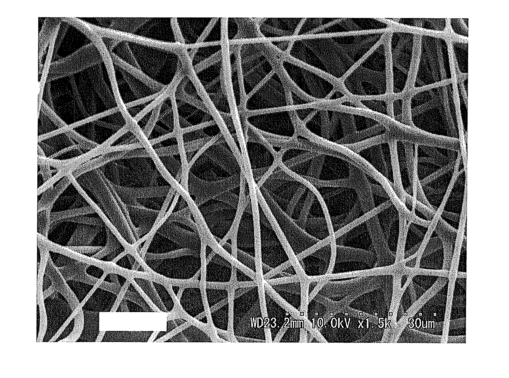
[0102]A fiber side face was inspected visually using a scanning electron microscope (SEM, S-3500N (trade name) manufactured by Hitachi, Ltd., magnification: 1500 times), and an average value was determined from the measurement results of randomly selected 30 monofilaments.

[0103]Mass Per Unit Area

[0104]Mass per unit area was measured according to JIS L 1906 (2000).

[0105]Thermal Shrinkage

[0106]In accordance with JIS L 1906 5.9.1, the temperature within the apparatus was set to 100° C., and thermal shrinkage in the lengthwise direction of the composite fiber was determined using a non-woven fabric test piece having a width of 20 cm and a length of 20 cm.

[0107]Tensile Strength

[010...

production examples 1 to 8

[0139]Table 1 below shows the island components or core components (first components) and the sea components or sheath components (second components) of source composite fibers used to produce ultrafine composite fibers of Production Examples 1 to 8, the proportion between the first component and the second component, the cross-sectional structure, the fiber diameter of a single monofilament, the total number of fibers, and the spinning flow rate. Ultrafine composite fibers of Production Examples 1 to 8 were obtained using the source composite fibers shown in Table 1 under the above-described spinning conditions. Note that the ultrafine composite fibers of Production Examples 1 to 5 had a cross section similar to the fiber cross sections of the source composite fibers. Table 1 also shows the fiber diameter of the ultrafine composite fibers of Production Examples 1 to 8 after spinning.

TABLE 1Source composite fiber (or source resin)Fiber diameterProductionIsland (core)Sea (sheath)Cros...

example 1

[0142]First, the ultrafine composite fiber of Production Example 1 was accumulated to obtain a fiber assembly (hereinafter referred to as a “spun non-woven fabric”). Next, the fiber assembly was heat-treated by a method using an air-through dryer at 145° C. for 30 seconds to produce a thermally-bonded non-woven fabric (hereinafter referred to as an “air-through dried non-woven fabric”), or was heat-treated by a method using a cylinder dryer at 140° C. for 30 seconds to produce a thermally-bonded non-woven fabric (hereinafter referred to as a “cylinder-dried non-woven fabric”).

[0143]Scanning electron micrographs (SEM, magnified 1500 times) of the surface of the spun non-woven fabric, the air-through dried non-woven fabric and the cylinder-dried non-woven fabric obtained in the manner described above are shown in FIGS. 9, 10 and 11, respectively.


PUM

PropertyMeasurementUnit
melting pointaaaaaaaaaa

Abstract

The present invention relates to a fiber assembly obtained by electrifying a resin in a melted state by application of voltage between a supply-side electrode and a collection-side electrode so as to extend the resin into an ultrafine composite fiber by electrospinning, and accumulating the ultrafine composite fiber, wherein the ultrafine composite fiber includes at least two polymeric components and the ultrafine composite fiber includes at least one type of composite fiber selected from a sea-island structure composite fiber and a core-sheath structure composite fiber as viewed in fiber cross section, at least one selected from an island component and a core component has a volume specific resistance of 1015Ω·cm or less, and at least one selected from a sea component and a sheath component has a volume specific resistance exceeding 1015Ω·cm. Thereby, the present invention provides a fiber assembly obtained by accumulating an ultrafine composite fiber obtained by electrospinning without the use of any solvent or water as a spinning solution, a composite of an electro conductive substrate and such a fiber assembly, and production methods thereof.

Description

TECHNICAL FIELD[0001]The present invention relates to a fiber assembly obtained using an electrospinning method, a composite of an electro conductive substrate and such a fiber assembly, and production methods thereof.BACKGROUND ART[0002]Conventionally, synthetic fibers including fibers of polyesters such as polyethylene terephthalate (PET), polyamide fibers such as nylon, and polyolefin fibers such as polyethylene and polypropylene generally are produced by a melt-spinning method. Ultrafine fibers such as nanofibers are known to be formed by splitting a sea-island fiber into nanofibers by removing the sea component of the sea-island fiber with the use of a solvent so as to leave the island component that will be nanofibers (Patent Document 1). Such ultrafine fibers have a small fiber diameter, and thus thermally-bonded non-woven fabrics made of the ultrafine fibers are suitable for use as clothing materials, automobile components and the like. For example, Patent Document 2 disclos...

Claims


Application Information

Patent Timeline
Patent Type & Authority Applications(United States)
IPC IPC(8): H01M2/16D04H13/00B32B5/02D01D5/12D01D5/08D01F8/06D01F8/10D04H1/728D04H3/016D04H3/02D04H3/147D04H3/153H01M4/02H01M50/403H01M50/417
CPCD01D5/0023Y10T428/2931D01D5/36D01F8/06D04H1/728D04H3/016D04H3/147H01M2/162H01M2/1673H01M4/13H01M4/139H01M4/661H01M10/0525Y02E60/122H01M2/145Y10T428/2929D01D5/34Y10T442/641Y10T442/638Y10T442/637Y10T442/64Y02E60/10H01M50/403H01M50/44H01M50/46H01M50/417Y02P70/50
Inventor KAMISASA, TOSHIO
Owner DAIWABO HLDG
Why Eureka
Try Eureka