Intravascular optical coherence tomography system with pressure monitoring interface and accessories

a technology of optical coherence tomography and optical coherence tomography, which is applied in the field of invasive medical devices, can solve the problems of monitoring systems, their susceptibility to electrical interference and calibration drift, and the relative large minimum diameter of pressure wires, and achieve cost-effective pressure monitoring capabilities

Active Publication Date: 2011-07-21
LIGHTLAB IMAGING
View PDF84 Cites 198 Cited by
  • Summary
  • Abstract
  • Description
  • Claims
  • Application Information

AI Technical Summary

Benefits of technology

[0008]The present invention relates to a method and apparatus for providing cost-effective pressure monitoring capabilities to an intravascular optical coherence tomography (OCT) system. The combined system permits convenient use of both modalities from a single system console in which processing, catheter control, and parameter and image display are controlled by software executing on the same computer.

Problems solved by technology

One drawback of electronic pressure measurement systems is the relatively large minimum diameter of the pressure wire, which is determined by the size of the transducer, wires, and wire attachment assembly.
A second drawback of electronic pressure monitoring systems is their susceptibility to electrical interference and calibration drift.
However in such an application, when intended to be used with imaging catheters, electronic pressure wires, because of their wire connections, are difficult to integrate with intravascular imaging catheters.

Method used


Image

  • Intravascular optical coherence tomography system with pressure monitoring interface and accessories
  • Intravascular optical coherence tomography system with pressure monitoring interface and accessories
  • Intravascular optical coherence tomography system with pressure monitoring interface and accessories

Examples


second embodiment

[0056]In the system to automatically determine what type of probe is connected to the system, following insertion of the catheter 86 or pressure probe 90, the system attempts to rotate the motorized fiber-optic rotary coupler 70. A torque sensor in the motor of the motorized coupler 70 measures resistance to rotation. Torque exceeding a specific threshold indicates that a pressure probe 90, with a non-rotating proximal connection, is attached. Once insertion of a pressure probe 90 has been detected, the motor disengages and the appropriate control and display software loads.

third embodiment

[0057]In a third embodiment, an encoded electrical or optical tag (e.g., bar code, wire-encoded electrical connector, RFID tag, flash memory chip) on the proximal end of the OCT imaging catheter 86 or pressure probe 90 (or both 82) is read by the system to identify the appropriate mode of operation. The tag can be read automatically by the probe interface 74 when the probe is inserted or, alternatively, a handheld device can be employed to read the marker from the body or package of the probe. This method of probe identification has the advantage that additional factory calibration data encoded in the markers can be read at the same time.

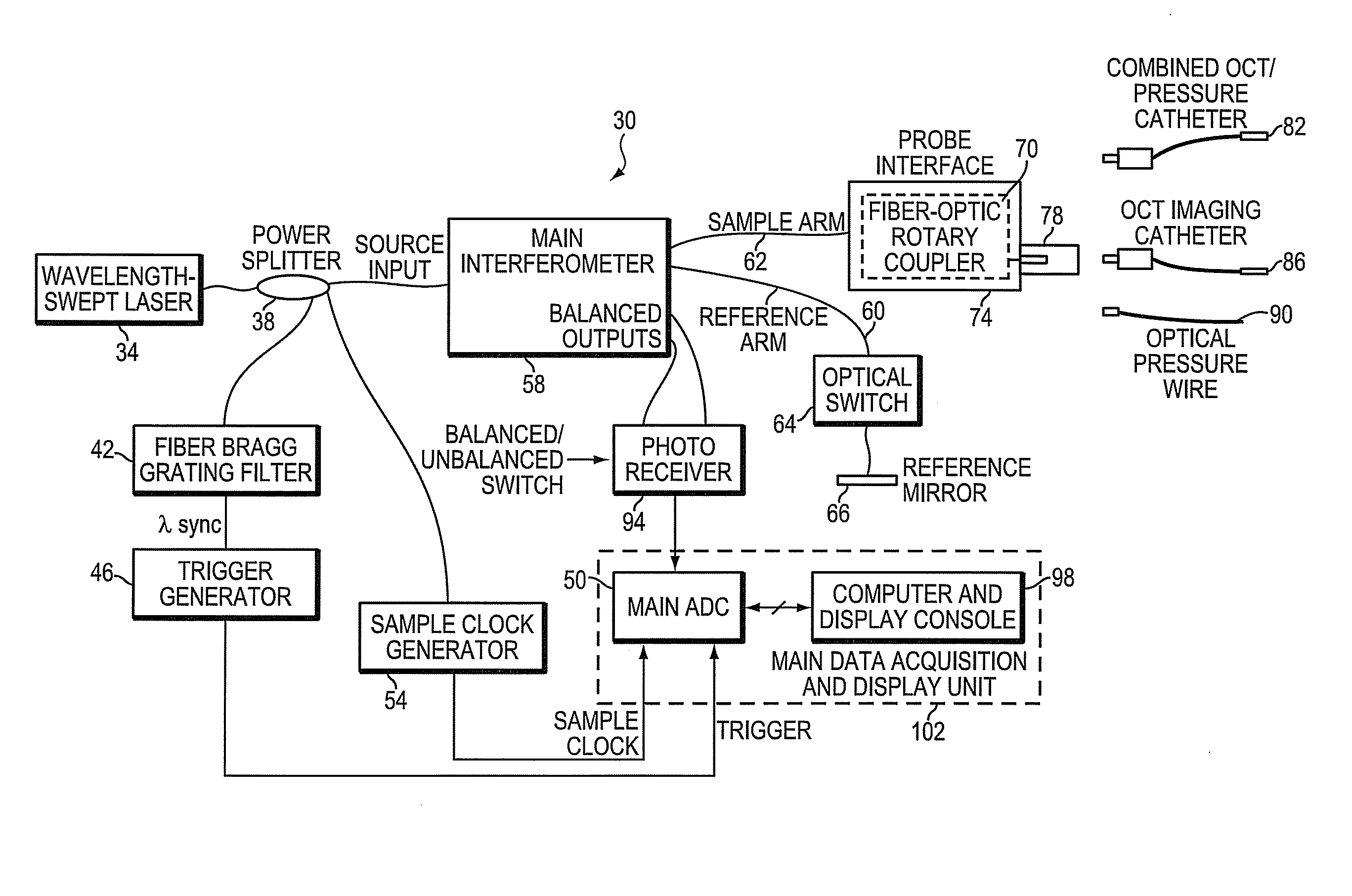
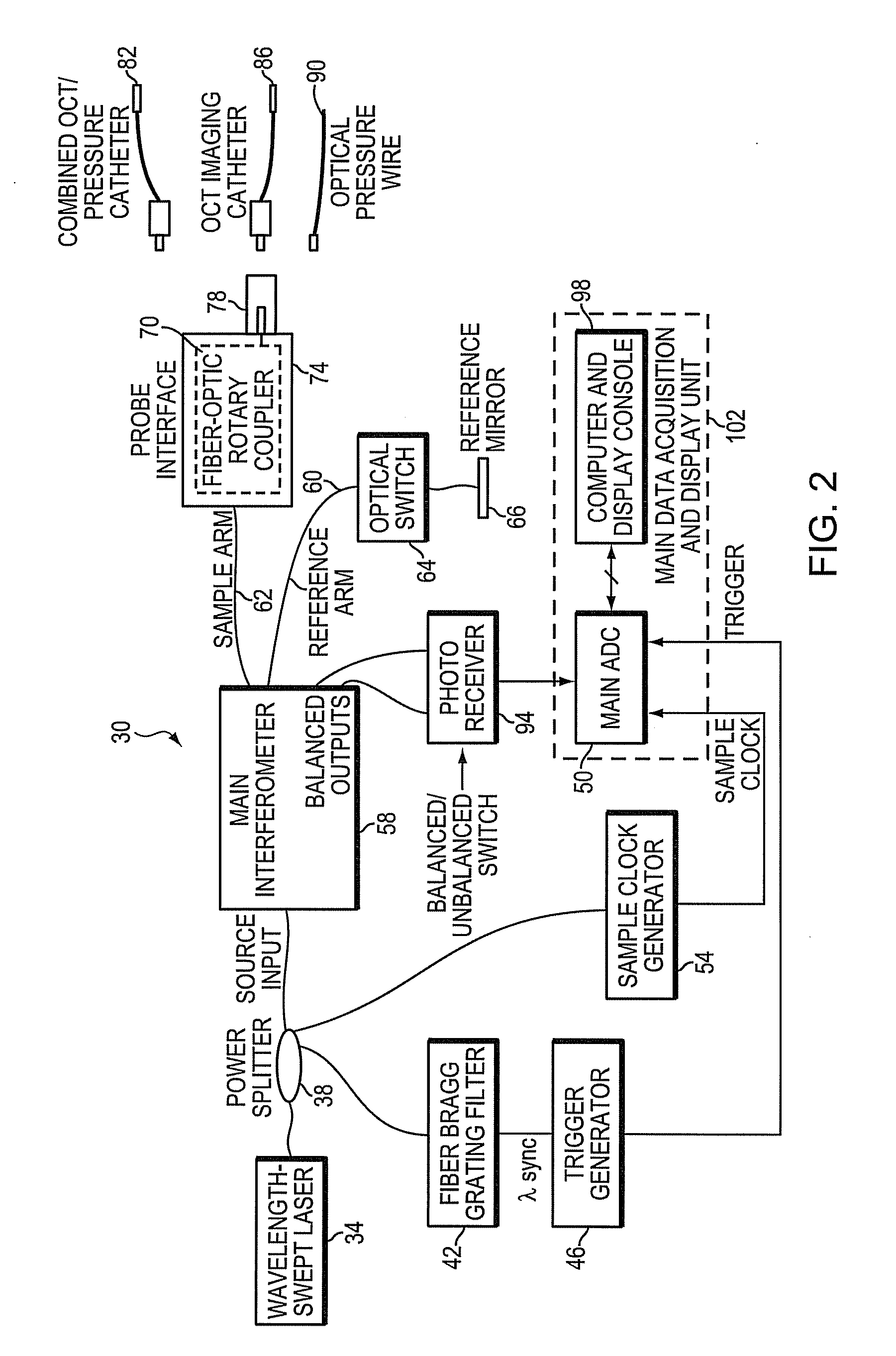
[0058]In addition to features that enable automatic software configuration, the system of FIG. 2 also contains features that enable automatic hardware configuration once the operational mode has been determined. In the standard OCT imaging mode, optical switch 64 is actuated, allowing light to reflect from the reference mirror 66. However, in the pr...

first embodiment

[0059]FIG. 3 is a block diagram of another embodiment 30′ of the invention in which separate optical connections are provided on the probe interface 74′ for the OCT imaging catheter 86 and optical pressure probe 90. This configuration enables acquisition of blood pressure measurements with a separate pressure probe 90 before, during, or after OCT imaging. Measurement of pressure during OCT imaging can be accomplished by inserting both probes in the blood vessel at the same time. An additional optical channel 112 from the power splitter 38′ directs light to the pressure probe 90 through an optical circulator 116. The optical circulator 116 re-directs the light that returns from the pressure probe 90 into a second photodetector 120 that generates the electronic signal corresponding to interference signals from which the pressure measurements are derived. These signals are digitized by a second channel of the analog to digital converter 50′ and recorded by the same data acquisition sys...


PUM

PropertyMeasurementUnit
distanceaaaaaaaaaa
lumen diametersaaaaaaaaaa
diameteraaaaaaaaaa

Abstract

An optical coherence tomography system and method with integrated pressure measurement. In one embodiment the system includes an interferometer including: a wavelength swept laser; a source arm in communication with the wavelength swept laser; a reference arm in communication with a reference reflector; a first photodetector having a signal output; a detector arm in communication with the first photodetector, a probe interface; a sample arm in communication with a first optical connector of the probe interface; an acquisition and display system comprising: an A / D converter having a signal input in communication with the first photodetector signal output and a signal output; a processor system in communication with the A / D converter signal output; and a display in communication with the processor system; and a probe comprising a pressure sensor and configured for connection to the first optical connector of the probe interface, wherein the pressure transducer comprises an optical pressure transducer.

Description

FIELD OF INVENTION[0001]This invention relates generally to invasive medical devices and more specifically to fiber-optic systems for imaging the lumen of blood vessels and for measuring physiological variables such as blood pressure.BACKGROUND[0002]The functional severity of a stenotic lesion in an artery can be assessed by measuring the pressure gradient across the lesion. Intravascular pressure measurement, particularly in the coronary arteries, has gained widespread acceptance as a tool for guiding catheter-based interventional procedures. Angioplasty or stenting of lesions in coronary arteries can be avoided if the fractional flow reserve (FFR), defined as the ratio of the blood pressures measured distal to and proximal to a lesion after injection of a vasodilating drug, exceeds a certain clinically defined threshold.[0003]Various devices have been developed for sensing arterial pressure at the tip of miniature catheters during medical diagnostic and interventional procedures. ...

Claims


Application Information

Patent Timeline
Patent Type & Authority Applications(United States)
IPC IPC(8): A61B6/00G01B11/02G01J3/45G01L11/02G02B6/00A61B5/02
CPCA61B5/0066A61B5/02007A61B5/0215A61B5/742A61B5/0075A61B5/0084A61B5/02154A61B5/6852
Inventor SCHMITT, JOSEPH M.PETROFF, CHRISTOPHER
Owner LIGHTLAB IMAGING
Why Eureka
Try Eureka