Undisturbed soil and sediment sampling

a sampling profile and soil technology, applied in the field of environmental sampling, can solve the problems of disturbing the sampling profile, driving up the cost of sampling, and time-consuming nature of collecting a reliable and credible sampl

Inactive Publication Date: 2011-07-28
DANESH BIJAN
View PDF5 Cites 83 Cited by
  • Summary
  • Abstract
  • Description
  • Claims
  • Application Information

AI Technical Summary

Benefits of technology

[0047]The torpedo tip may be screwed together with the initial sampling tube, and the tightening of the vertical space is performed by applying a rotational force for further screwing the initial sampling tube and the torpedo tip together. The torpedo tip includes fin structures for preventing the torpedo tip from turning inside the formation while the initial sampling tube is rotated, and the lowering is performed using a translational up and down motion. The compressing causes an upper portion of the sampled core to dissociate from a portion below a compressed zone, and the compressed zone functions as a cap for the upper portion of the sampled core preventing the upper portion from falling out of the sampling tubes. The compressing may be performed by tightening of a vertical space between the initial sampling tube and the torpedo tip and creating an inward bulge in a spacer located within the vertical space. The spacer may be an O-ring. The lowering may be performed by a continuous and controllable force that is pneumatically driven, pulley and winch driven or driven by a combination of both, and the lowering is assisted by vibratory action for penetrating through coarse particulate matter.
[0048]Aspects of the present invention provide a method for collecting samples from a formation. The method includes attaching a leading device to a sampling tube, the leading device being susceptible to a translational downward motion into the soils or sediments and being resistant to a rotational motion while within the soils or sediments, driving the sampling tube into the soils or sediments by the translational downward motion, reaching a desired sampling depth, rotating the sampling tube to cause a tightening of a vertical space between the sampling tube and the leading device, and withdrawing the sampling tube and the attached leading device by a translational upward motion. The tightening of the vertical space between the sampling tube and the leading device causes a structural weakness in a sampled core at or near a location of connection between the sampling tube and the attached leading device.

Problems solved by technology

A detailed literature review of the current sampling techniques and core sampling equipment demonstrates substantial inefficiencies and difficulties that cause inaccuracies in the sampling results and drive up the cost of sampling.
There are many disadvantages associated with the available samplers, such as limitations with required force to drive the sampler to desired depths, disturbing of the sampling profile due to vibration, difficulties associated with retaining the sample in the sampling device, errors associated with drift of the sampler during deployment, the time consuming nature of collecting a reliable and credible sample, and the excessive cost associated with inefficiencies of the existing samplers.
(1) The loss of the surface layer of sediments at the moment of penetration due to poor draining of the water inside the corer or increased pressure on the cutting head, particularly during a high-speed freefall.
(5) The contamination of the lower horizons due to internal washout of material from the bottom of the core during recovery due to the lack of a core retention system, excessive ascent speed or malfunction of the top valve.

Method used


Image

  • Undisturbed soil and sediment sampling
  • Undisturbed soil and sediment sampling
  • Undisturbed soil and sediment sampling

Examples


Embodiment Construction

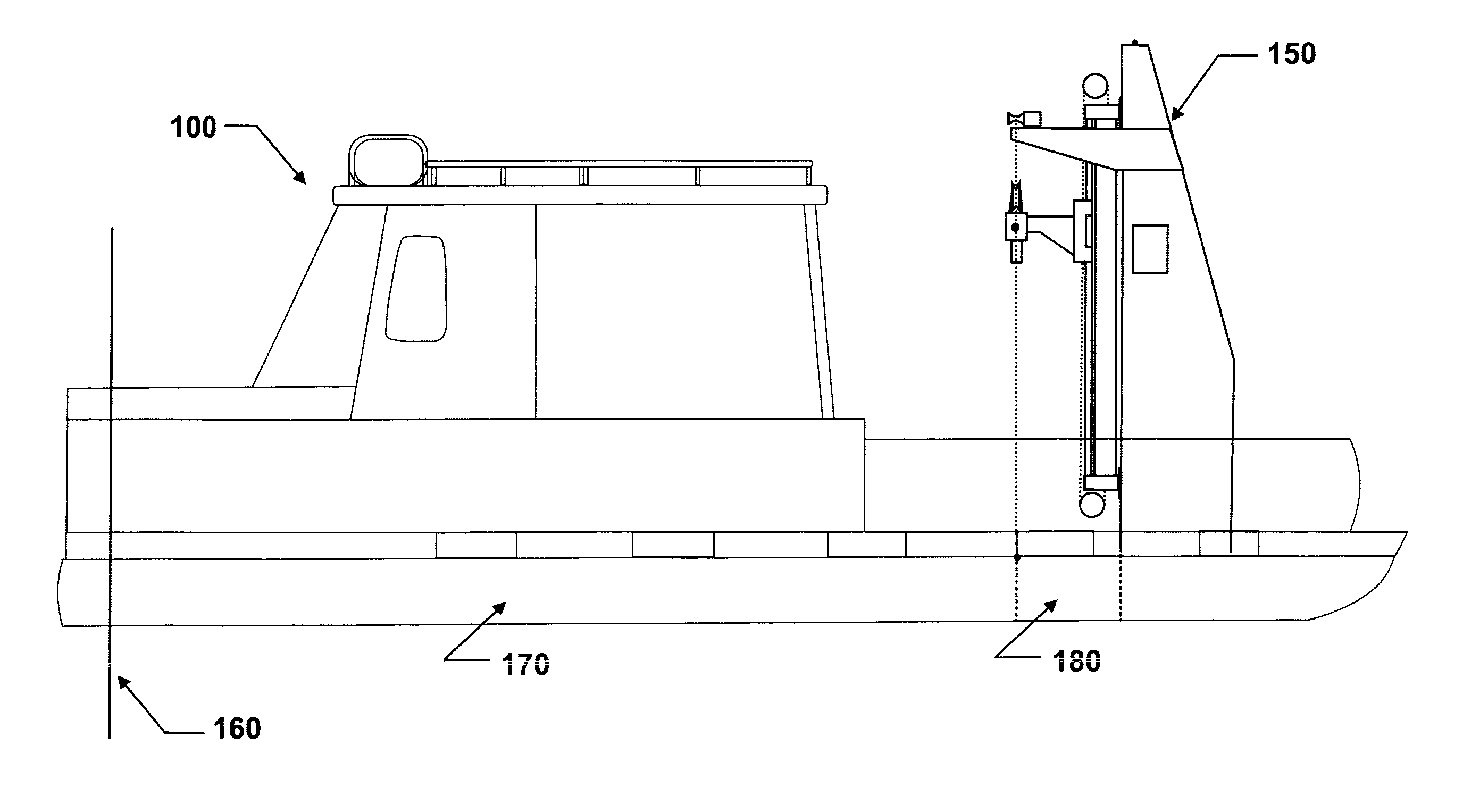
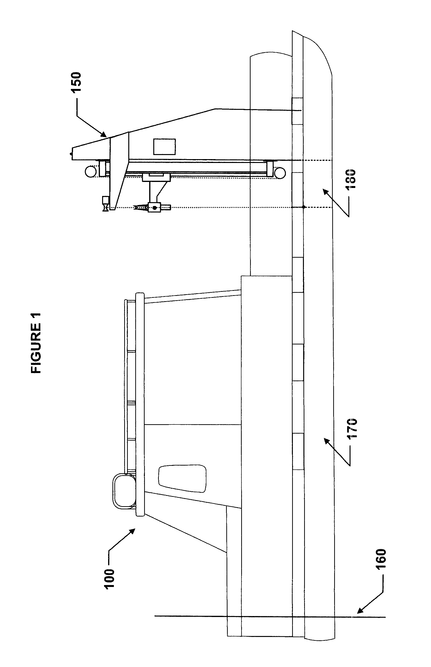
[0067]The present invention presents systems, devices and methods for substantially undisturbed sampling of soil and sediments including soft underwater sediments. This invention implements undisturbed sample collection for use in numerous science and engineering fields including environmental science and engineering, civil and geotechnical engineering, hydrogeology, oceanographic sampling, mining explorations, archeology and geology.

[0068]In the following written description, soil is generally used to refer to formations on land and sediments are generally used to refer to deposits under a body of water. However, so much of dry land was at one point formed below water. As such, the term formation is used to refer to soils and sediments whether in dry land, saturated soil or vadoze zone. Further, a system built according to the aspects of the present invention may be installed upon and transported on a barge, a truck or any other type of vehicle.

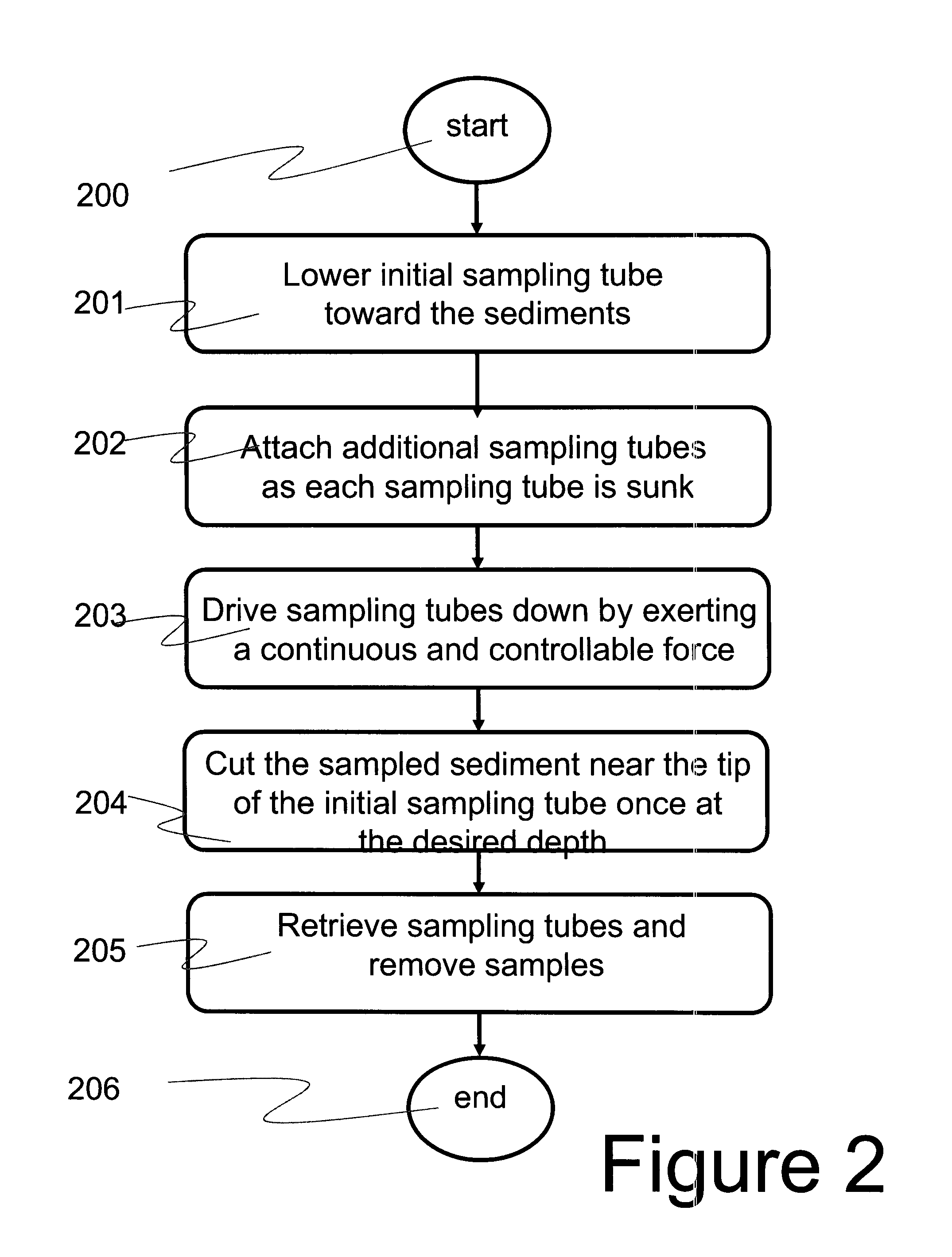
[0069]Core sampling disturbs a portio...


PUM

PropertyMeasurementUnit
angleaaaaaaaaaa
depthaaaaaaaaaa
forceaaaaaaaaaa

Abstract

Device, system and method for sampling of soft sediments with retention of sample material and profile. A barge is anchored and stabilized in position; sampling tubes are driven through underlying sediments using continuous and controllable translational pneumatic force; a torpedo-shaped end piece leads the sampling tubes into the sediments. Once at desired depth, a rotational force is applied to sampling tubes. Fins located around torpedo prevent the torpedo from rotating and connection between leading sampling tube and torpedo is tightened. O-ring located between torpedo and leading sampling tube is squeezed as a result of such tightening and bulges inward pinching the core inside sampling tube. During retrieval, core is more likely to break at the location of the pinch which has introduced structural discontinuity; core above the pinch is capped by compacted material at the pinch. O-ring does not disturb sample integrity during descent. Winch and pulley mechanism may assist.

Description

BACKGROUND OF THE INVENTION[0001]1. Field of the Invention[0002]The present invention pertains generally to the field of environmental sampling and, more particularly, to sampling of soft soils or sediments.[0003]2. Description of Related Art[0004]Industrial, agricultural, recreational, and waste disposal activities introduce hazardous contaminants into air, water, and soil. These contaminants pose immediate hazards or are capable of posing future hazards to man and the ecosystem. Contaminants become hazardous when they exceed certain permissible background levels, predetermined to be protective of human health and ecological health. When the permissible background concentrations are exceeded, site cleanup is required. Site clean up, or remediation, involves the removal, reduction, immobilization or neutralization of contaminants. This, in effect, reduces the adverse impact of the contaminants on human health and safety and the environment. Remediation is a multi-stage process which...

Claims


Application Information

Patent Timeline
Patent Type & Authority Applications(United States)
IPC IPC(8): G01N1/08
CPCG01N1/08G01N2001/1006G01N1/10
Inventor DANESH, BIJAN
Owner DANESH BIJAN
Why Eureka
Try Eureka