Thermal detector, thermal detector device, electronic instrument, and method of manufacturing thermal detector
- Summary
- Abstract
- Description
- Claims
- Application Information
AI Technical Summary
Benefits of technology
Problems solved by technology
Method used
Image

Examples
first embodiment
[0059]The description turns first to the planar shape and to the three-dimensional structure of the transverse cross-section of a support member.
Planar Shape and Three-Dimensional Structure of Transverse Cross-Section of Support Member
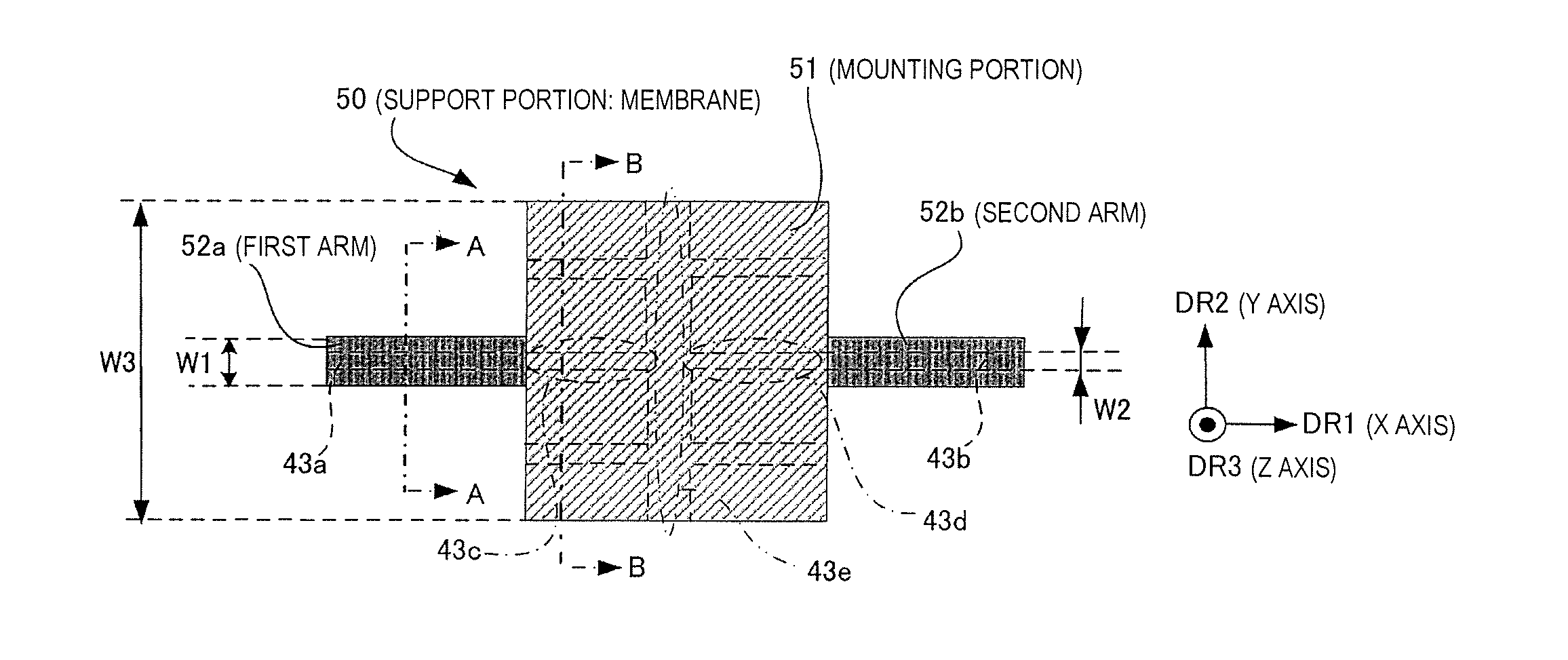
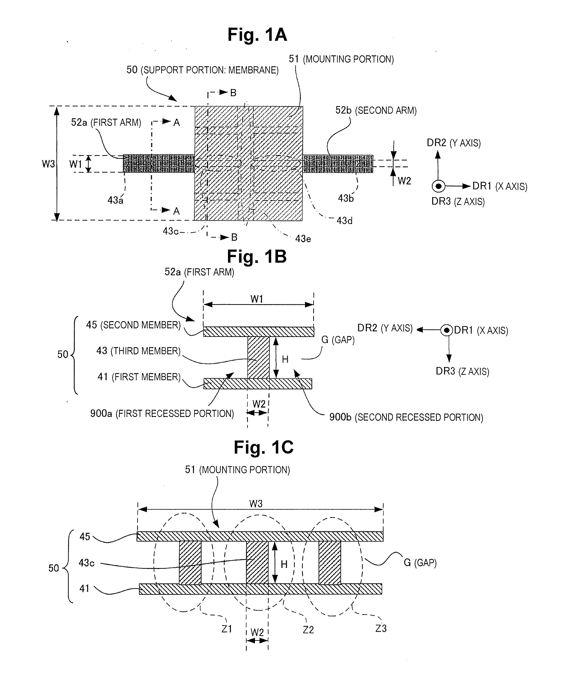
[0060]FIG. 1A to FIG. 1C are drawings illustrating the planar shape and the cross-sectional structure of a support member (membrane) in a thermal detector. FIG. 1A is a drawing showing the shape (in partial perspective view) of a support member (membrane) in a thermal detector; FIG. 1B is a cross-sectional view along line A-A (transverse cross-section of first arm); and FIG. 1C is a cross-sectional view along line B-B (transverse cross-section of mounting portion).
[0061]The support member (membrane) 50 is formed, for example, through superposition of a plurality of films, and has a shape in transverse cross-section that is a three-dimensional structure. This support member 50 supports a thermal detector element (not shown in FIG. 1) above a cavity for ...
second embodiment
[0096]FIG. 5 is a drawing showing a modified example of a transverse cross-sectional shape of a support member. In the example of FIG. 5, in the three-dimensional shape of the transverse cross-section of the support member 50, the second sacrificial layer has not been completely removed and a portion still remains. This remaining portion of the second sacrificial layer is denoted by reference symbol 80′ in FIG. 5. The second sacrificial layer 80′ functions as a reinforcing member. Due to the remaining second sacrificial layer 80′, for example, the surface area of the section supporting the third member 45 is larger, and the mechanical strength of the H-type structure is enhanced.
third embodiment
[0097]In the present embodiment, in addition to the aforementioned structure for reducing the thermal capacity of the support member 50 per se, supporting support posts are utilized in order to reduce flexion of the support member and avoid problems such as sticking. Where the support member 50 is made thinner in order to reduce the thermal capacity, during the manufacturing process if, for example, wet etching is used to form the cavity for thermal separation purposes, there arises a susceptibility to sticking (adhesion (bonding) between the substrate and the support member. Sticking can arise, for example, from surface tension of the liquid during the drying process subsequent to wet etching.
[0098]In order to avoid sticking, it is preferable to provide auxiliary support posts for stable support of the support member during the manufacturing process; however, where auxiliary support posts are simply provided, these will function as pathways for heat transmission, and therefore ther...
PUM
| Property | Measurement | Unit |
|---|---|---|
| Thickness | aaaaa | aaaaa |
| Width | aaaaa | aaaaa |
| Height | aaaaa | aaaaa |
Abstract
Description
Claims
Application Information
 - Generate Ideas
- Intellectual Property
- Life Sciences
- Materials
- Tech Scout
- Unparalleled Data Quality
- Higher Quality Content
- 60% Fewer Hallucinations
Browse by: Latest US Patents, China's latest patents, Technical Efficacy Thesaurus, Application Domain, Technology Topic, Popular Technical Reports.
© 2025 PatSnap. All rights reserved.Legal|Privacy policy|Modern Slavery Act Transparency Statement|Sitemap|About US| Contact US: help@patsnap.com