Method and apparatus for designing and/or implementing variable flip angle MRI spin echo train

a technology of magnetic resonance imaging and spin echo train, which is applied in the direction of reradiation, measurement using nmr, instruments, etc., can solve the problems of nontrivial objectives to be met, nontrivial design constraints, and limited effectiveness of extended phase graph algorithm, so as to improve the management of the entire rf echo train design

Active Publication Date: 2011-07-28
TOSHIBA MEDICAL SYST CORP
View PDF1 Cites 16 Cited by
  • Summary
  • Abstract
  • Description
  • Claims
  • Application Information

AI Technical Summary

Benefits of technology

[0031]The exemplary embodiments track the evolution and management of the main spin-locked component of the magnetization signal. Accordingly, they should not lead to unstable train designs (i.e., dominated by a signal far away from equilibrium conditions). The exemplary techniques also can, in effect, ignore artifact-laden signal pathways. For example, when T1ρ or low-frequency dispersion effects are different than simple T2 effects, the exemplary embodiments herein may be more accurate than T2 models—and may allow for better management of the entire RF echo train design.

Problems solved by technology

When a series of echoes is to be achieved, there are nontrivial design constraints and nontrivial objectives to be met.
Such a target may or may not be feasible.
It could be infeasible because signal decay (relaxation) of NMR magnetization is such that not enough magnetization signal persists later in an echo train.
The extended phase graph algorithm can be limited in effectiveness in that it normally only applies to trains with uniform echo spacing, matched gradient moments per each inter-echo interval, and so forth.
Algorithms that depend upon T1 and T2 in the simulation models also may not fully describe complex tissues.
Either of these forward calculation methods also has a chance of producing progressively increasing error in a VFA RF refocusing pulse amplitude design, as the echo signal train is calculated from echo-to-echo, especially as the signal level becomes nearly unfeasible and the remaining magnetization is nearly exhausted due to relaxation.

Method used


Image

  • Method and apparatus for designing and/or implementing variable flip angle MRI spin echo train
  • Method and apparatus for designing and/or implementing variable flip angle MRI spin echo train
  • Method and apparatus for designing and/or implementing variable flip angle MRI spin echo train

Examples


Embodiment Construction

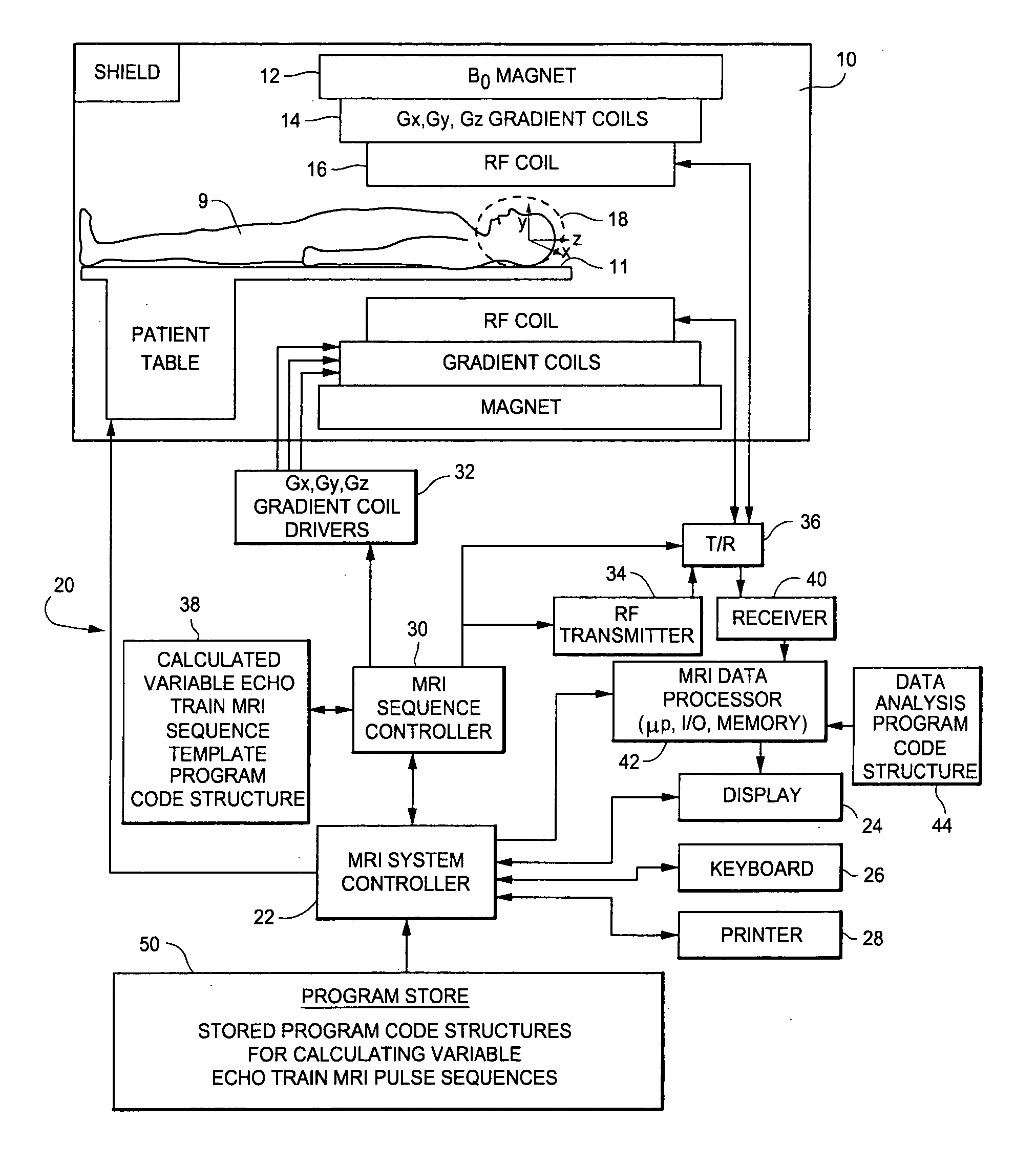
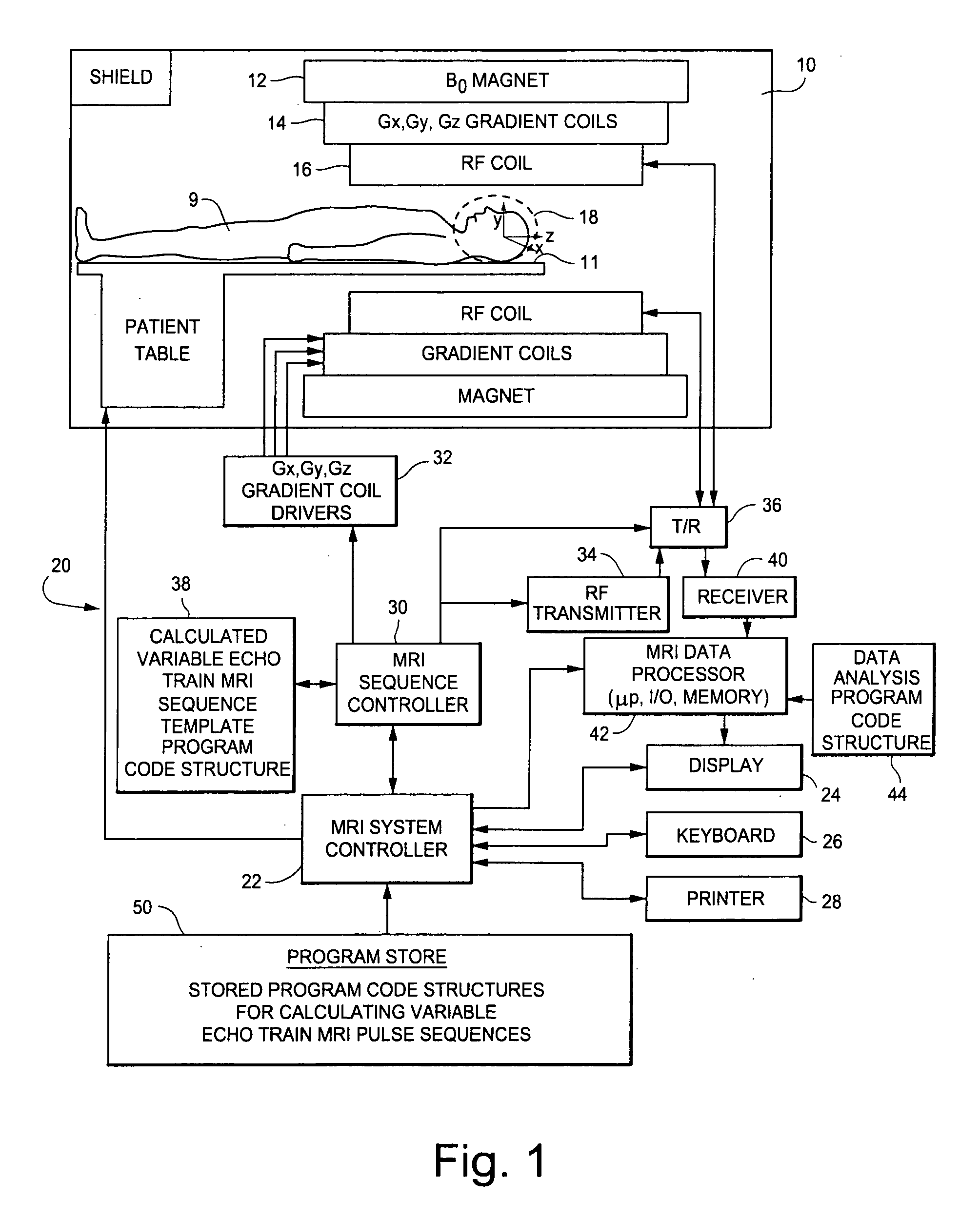
[0049]The MRI system shown in FIG. 1 includes a gantry 10 (shown in schematic cross-section) and various related system components 20 interfaced therewith. At least the gantry 10 is typically located in a shielded room. One MRI system geometry depicted in FIG. 1 includes a substantially coaxial cylindrical arrangement of the static field Bo magnet 12, a Gx, Gy and Gz gradient coil set 14 and an RF coil assembly 16. Along the horizontal axis of this cylindrical array of elements is an imaging volume 18 shown as substantially encompassing the head of a patient 9 supported by a patient table 11.

[0050]An MRI system controller 22 has input / output ports connected to display 24, keyboard 26 and printer 28. As will be appreciated, the display 24 may be of the touch-screen variety so that it provides control inputs as well.

[0051]The MRI system controller 22 interfaces with MRI sequence controller 30 which, in turn, controls the Gx, Gy and Gz gradient coil drivers 32, as well as the RF transm...


PUM


Abstract

A variable flip angle (VFA) MRI (magnetic resonance imaging) spin echo train is designed and / or implemented. For example, a target train of detectable spin-locked NMR (nuclear magnetic resonance) echo signal amplitudes may be defined and a corresponding designed sequence of variable amplitude (i.e., variable NMR nutation angle) RF refocusing pulses may be determined for generating that target train of spin echoes in an MRI sequence (e.g., used for acquiring MRI data for a diagnostic imaging scan or the like). Such a designed VFA sequence may be output for study and / or use by an MRI system sequence controller.

Description

[0001]An appendix comprising a sixteen-page computer program listing is submitted concurrently herewith on duplicate compact discs (CD-ROMs) and is hereby incorporated by reference into this specification in accordance with 37 C.F.R. §1.52(e)(5). This incorporated appendix comprises a single file (dannelsprogram.pdf—created Jan. 27, 2010—468 KB) containing the images of a sixteen-page listing of a computer program exemplary embodiment written in IDL (Interactive Data Language) source code.BACKGROUND[0002]1. Technical Field[0003]This application describes method and apparatus for designing and / or implementing a variable flip angle (VFA) MRI (magnetic resonance imaging) spin echo train. For example, a target train of detectable spin-locked NMR (nuclear magnetic resonance) echo signal amplitudes may be defined and a designed sequence of variable amplitude (i.e., variable NMR nutation angle) RF refocusing pulses may be determined for generating that target train of spin echoes in an MRI...

Claims


Application Information

Patent Timeline
Patent Type & Authority Applications(United States)
IPC IPC(8): G01R33/48
CPCG01R33/5617
Inventor DANNELS, WAYNE R.
Owner TOSHIBA MEDICAL SYST CORP
Why Eureka
Try Eureka