Power supply device with battery cell cooling mechanism and vehicle including the same

Active Publication Date: 2011-07-28
SANYO ELECTRIC CO LTD
View PDF8 Cites 31 Cited by
  • Summary
  • Abstract
  • Description
  • Claims
  • Application Information

AI Technical Summary

Benefits of technology

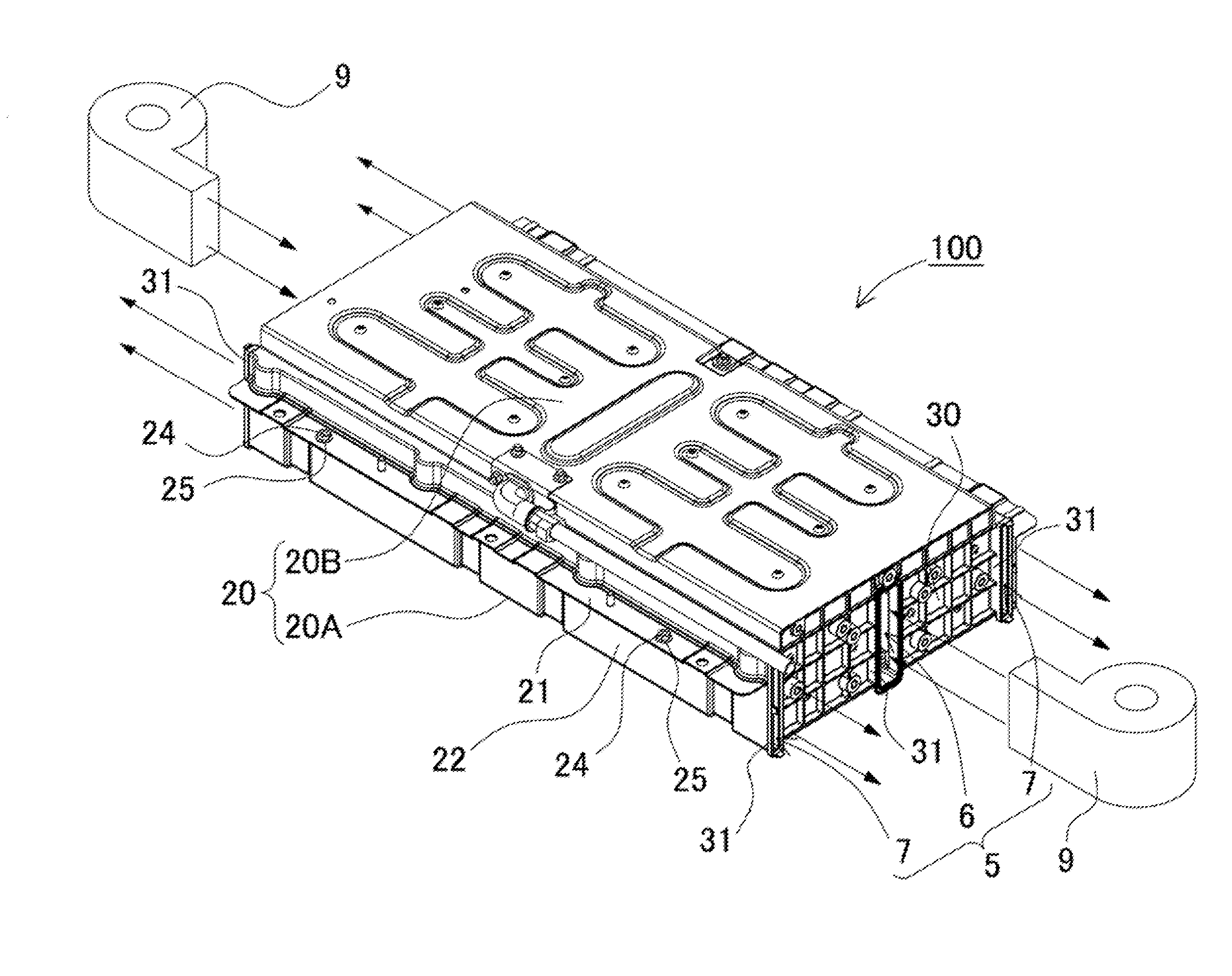
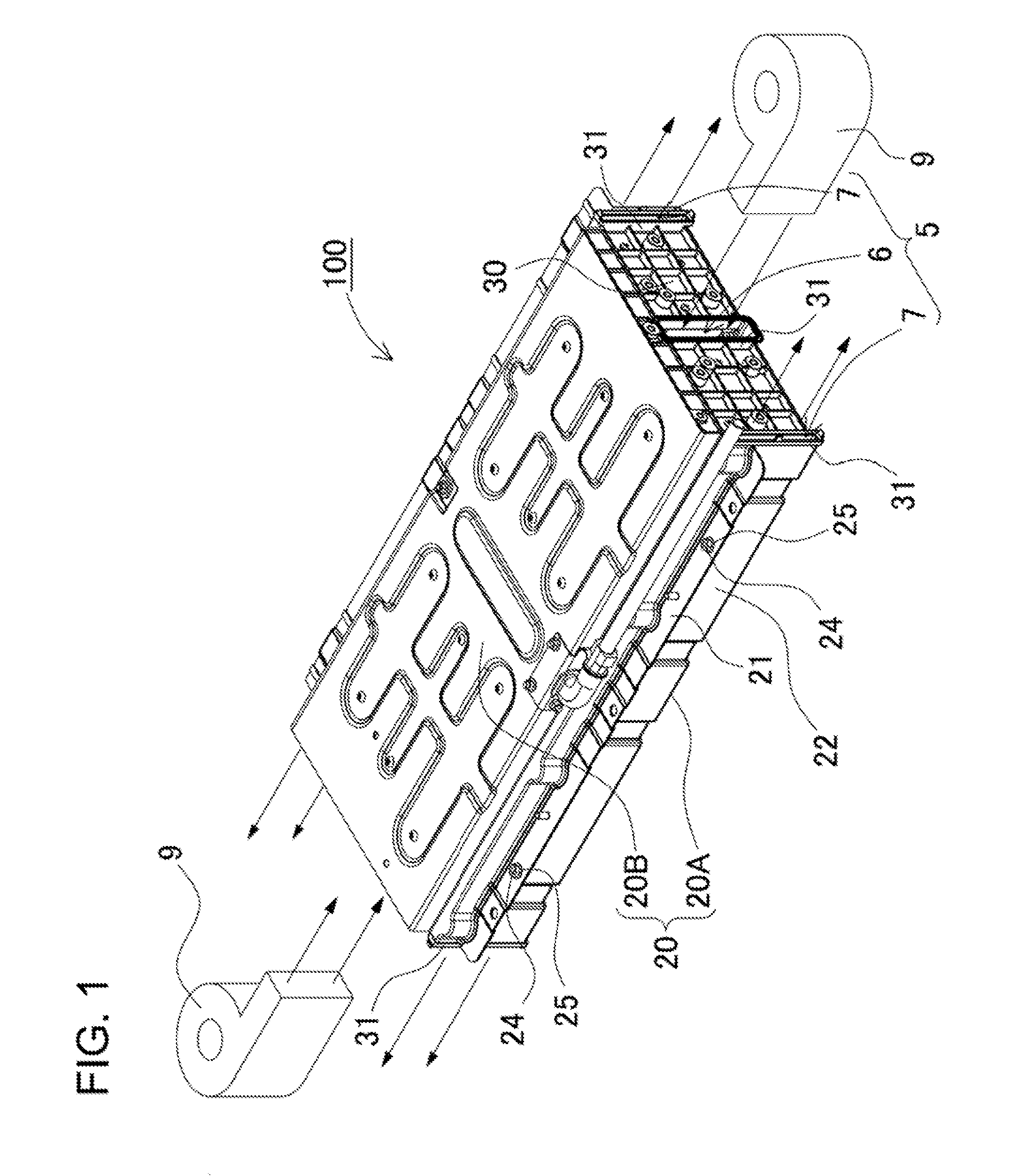
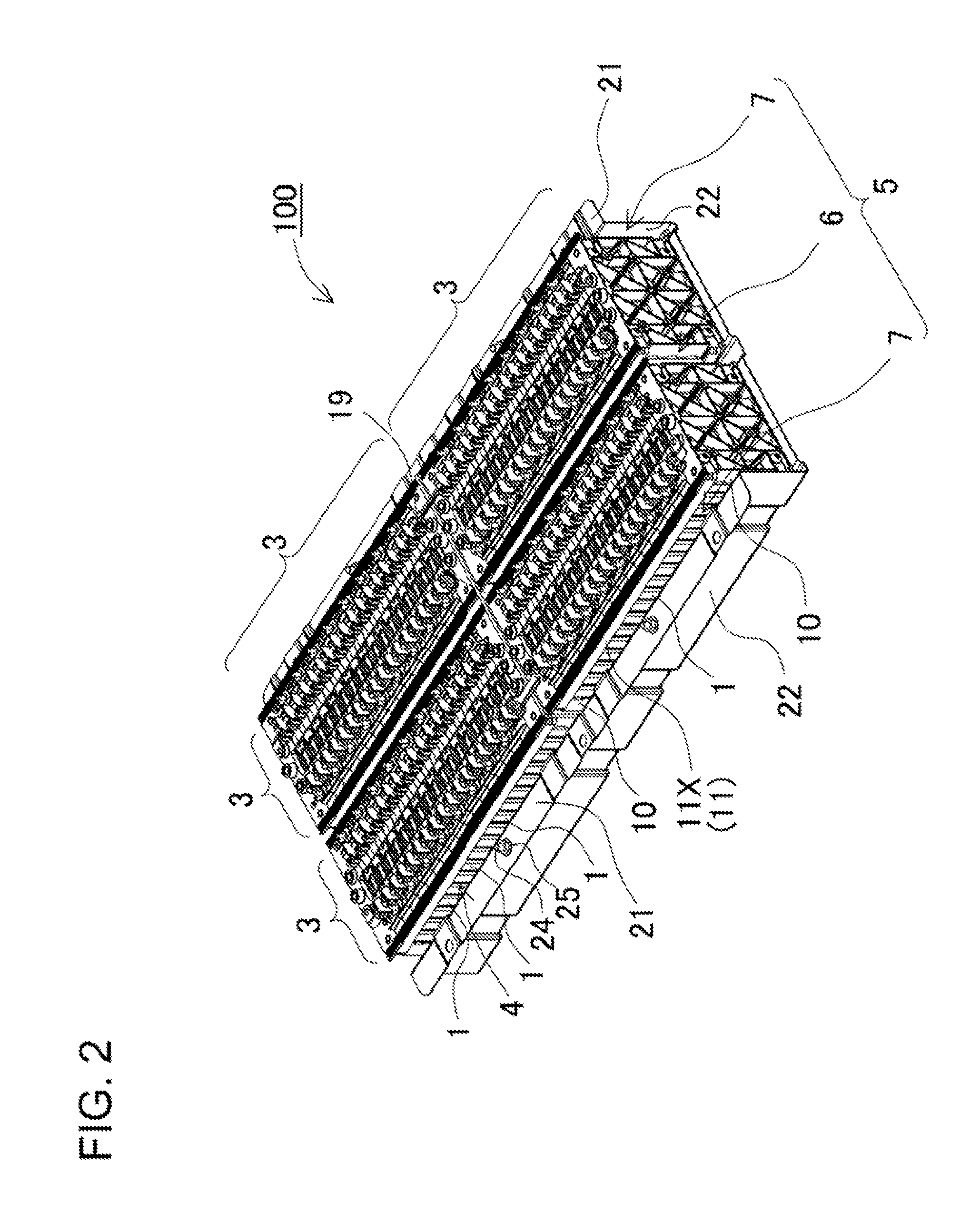
[0013]To achieve the above object, a power supply device according to a first aspect of the present invention includes a battery block 3, coupling members 11, and a temperature equalizing plate 15. The battery block 3 includes a plurality of battery cells 1 arranged side by side. The cooling gaps 4 are formed for flowing cooling gas between battery cells 1. The coupling members 11 extend in the side-by-side arrangement direction of the battery cells 1, and couple the plurality of battery cells 1 to each other in the side-by-side arrangement. The temperature equalizing plate 15 is arranged on a side surface of the battery block 3, and at least partially closes openings of some of the cooling gaps 4 on the cooling gas inlet side of the cooling gaps 4. The cooling gas is blown from the side surface of the battery block 3 into the cooling gaps 4 so that the battery cells 1 are cooled. The temperature equalizing plate 15 covers the side surface of the battery block 3. The width of the temperature equalizing plate 15 varies so that the amounts of the cooling gas flowing into the cooling gaps 4 is reduced as the battery cells are located closer to the cooling gas upstream side. The cooling gas upstream side of the temperature equalizing plate 15 is fastened to the battery block 3. The temperature equalizing plate 15 includes attachment pro

Problems solved by technology

In particular, in the case where the number of the battery cells arranged side by side is large, it is difficult to cool all the battery cells to uniform temperatures, in other words, to temperatures that fall within a small range.
The reason is that temperature difference may cause uneven remaining capacities of the battery cells, and as a result deteriorate the life of some battery cells.
If the batteries have different remaining capacities, when a battery is likely to have a larger remaining capacity, the battery is likely to be overcharged.
On the other hand, when another battery is likely to have a smaller remaining capacity, the battery is likely to be over-discharged.
If a battery is overcharged or over-discharged, the battery will deteriorate faster.
As a result, the life of the vehicle battery system will be reduced.
In particular, in the case of the vehicle battery system for hybrid car, plug-in hybrid car, electric vehicle and the like, since a number of side-by-side arranged batteries are provided to be charged/discharged at a large amount of current, its manufacturing cost will be very expensive.
In particular, as the number of batteries used in the vehicle battery system increases, its manufacturing cost increases.
Contrary to this, as the number of side-by-side arranged batteries increases, temperature difference in the vehicle battery system will increase, which in turn may red

Method used


Image

  • Power supply device with battery cell cooling mechanism and vehicle including the same
  • Power supply device with battery cell cooling mechanism and vehicle including the same
  • Power supply device with battery cell cooling mechanism and vehicle including the same

Examples


embodiment 2

[0068]In the aforementioned power supply device has been described that includes the inlet duct arranged between the battery blocks arranged in parallel to each other, and the outlet ducts arranged outside the battery blocks so that cooling gas is blown from the central part to the outside parts of the power supply device. However, the construction for blowing cooling gas to the battery block is not limited to this construction. For example, the inlet ducts can be arranged outside the battery blocks, while outlet duct can be arranged between the battery blocks so that cooling gas is blown from the outside parts to the central part of the power supply device. FIG. 8 shows this type of power supply device as an embodiment 2. In the power supply device 200 according to the embodiment 2 shown in FIG. 8, inlet ducts 56 are arranged in parts outside the two rows of battery blocks 3, and an outlet duct 57 is arranged in the part between the two rows of battery blocks 3 and communicates wit...

embodiment 3

[0072]The aforementioned power supply device has been described that includes the battery blocks 3, which are arranged in parallel to each other in two rows, and the air ducts 5 and 55, which are arranged in a part between the two rows of battery blocks 3 and in parts outside the two rows of battery blocks 3. However, the power supply device can be composed of one row of battery blocks. In the power supply device 300 according to an embodiment 3 shown in FIG. 9, two air ducts 75 are arranged on the both sides of one row of battery blocks 3. One of the two air ducts 75 serves as an inlet duct 76, while the other of the two air ducts 75 serves as an outlet duct 77. In this power supply device 300, as shown by arrows in FIG. 9, cooling gas is forcedly blown from the inlet duct 76 toward the outlet ducts 77 by the blower mechanism 9 to cool the battery cells 1. The cooling gas is forcedly blown from the inlet ducts 76, and then cooling gas flows pass through the cooling gaps 4 to cool t...


PUM


Abstract

A power supply device includes a battery block 3 of battery cells 1. Cooling gaps 4 are provided for flowing cooling gas between cells 1 from a side surface of the block 3 into the gaps 4. The width of a temperature equalizing plate 15 covering the side surface of the block 3 varies designed so that the amounts of the gas flowing into the gaps 4 are reduced toward the upstream side. The upstream side of the plate 15 is fastened to the block 3. The plate 15 includes protrusions 37 that protrude from the downstream side of the plate 15. Insertion portions 39 are arranged at positions of coupling members 11 corresponding to the protrusions 37 on side surface of the block 3. When the protrusions 37 of the plate 15 are inserted into the insertion portions 39, the plate 15 is attached to the coupling members 11.

Description

BACKGROUND OF THE INVENTION[0001]1. Field of the Invention[0002]The present invention relates to a power supply device that includes a plurality of battery cells arranged side by side with separators being interposed between the battery cells, and a vehicle using the power supply device.[0003]2. Description of the Related Art[0004]A power supply device or a battery system has been developed that includes a number of battery cells arranged side by side, and forcedly blows cooling air to cooling gaps between the battery cells. This type of power supply device or battery system is used for vehicles such as hybrid car and electric vehicle. Since this type of power supply device employs a number of battery cells, the battery cells will have temperature difference among them. In particular, in the case where the number of the battery cells arranged side by side is large, it is difficult to cool all the battery cells to uniform temperatures, in other words, to temperatures that fall within...

Claims


Application Information

Patent Timeline
IPC IPC(8): H01M10/50B60K11/06B60L50/16H01M10/60H01M50/209H01M50/227H01M50/271
CPCB60L3/0046B60L11/1874B60L11/1879H01M2/1077H01M10/5008Y02T10/705H01M10/5032H01M10/5053H01M10/5067H01M10/5073Y02T10/7005H01M10/5016H01M10/625H01M10/6563H01M10/647H01M10/6554H01M10/617H01M10/6566B60L58/26B60L50/64B60L58/18Y02T10/70Y02E60/10H01M50/227H01M50/271H01M50/209
Inventor OKADA, WATARU
Owner SANYO ELECTRIC CO LTD
Why Eureka
Try Eureka