Ratchet-type tensioner

a tensioner and ratchet technology, applied in the direction of belts/chains/gearings, mechanical equipment, belts/chains/gearings, etc., can solve the problems of excessive chain strain, restrict the retracting movement of the plunger, increase the noise generated by the chain as it travels, etc., to reduce the flapping noise generated by the timing chain, reduce backlash, and high load

Inactive Publication Date: 2011-07-28
TSUBAKIMOTO CHAIN CO
View PDF9 Cites 13 Cited by
  • Summary
  • Abstract
  • Description
  • Claims
  • Application Information

AI Technical Summary

Benefits of technology

[0008]This invention addresses the above-described problems by providing a ratchet-type tensioner capable of blocking plunger backlash on engine start-up, avoiding flapping noise, and preventing seizing of the plunger, but without restricting retracting movement of the plunger caused by excessive tension in the timing after engine start-up.
[0011]This aspect of the invention makes it possible restrict backlash, and to reduce flapping noises generated by the timing chain. In addition, the invention avoids the need for a special plunger biasing spring capable of accommodating a high load, and avoids the need for an orifice mechanism or oil reserve mechanism. Consequently, it does not require a large number of parts, and its manufacturing cost is low. The invention also makes it possible to downsize a tensioner while still achieving all of the capabilities of a larger tensioner.
[0012]The invention also makes it possible for the ratchet piston to disengage the rack teeth on the plunger allowing the plunger to retract when the tension in the chain becomes excessive after starting the engine. Retraction can occur until the force exerted by the rack teeth on the ratchet in the direction of ratchet movement falls below the force exerted by the ratchet-biasing spring, at which time the ratchet teeth again block retraction of the plunger.
[0013]Seizing of the plunger is avoided by permitting retraction of the plunger. Furthermore, by adjusting the biasing force exerted by the ratchet-biasing spring, it is possible to adjust the tensioner so that disengagement of its ratchet mechanism occurs when the tension in the timing chain reaches a particular level. In this way, the timing of disengagement caused by excessive tension of the chain after starting the engine can be adjusted.
[0014]Preferably the rack teeth of the plunger are concave-convex teeth defined by inclined planes facing in the direction of plunger retraction and inclined planes facing in the direction of plunger protrusion, and the ratchet teeth are also concave-convex teeth defined by inclined planes facing in the direction of plunger retraction, and inclined planes facing in the direction of plunger protrusion. Accordingly, it is possible to permit smooth, unrestricted, retraction of the plunger while preventing wear chipping of rack teeth and the ratchet teeth, and to avoid excessive shock from being applied to the ratchet-biasing spring, thereby improving the durability of the tensioner.
[0015]When the rack teeth are defined by steeply inclined planes facing in the direction of plunger retraction and more gradually inclined planes facing in the direction of plunger protrusion, and the ratchet teeth are defined by gradually inclined planes facing in the direction of plunger retraction, and more steeply inclined planes facing in the direction of plunger protrusion, it becomes possible to prevent retraction of the plunger on starting an engine, and to allow retraction of the plunger when timing chain tension becomes excessive after engine start up, using a simple, inexpensive, and reliable mechanism.

Problems solved by technology

A problem with the prior art tensioner described above is that, the mutually engaging planes of teeth 536 and the teeth of rack 538 that block retracting movement of the plunger are orthogonal to the direction of movement of the plunger, they also restrict retracting movement of the plunger 514 that occurs due to excessive tension of the chain resulting from causes such as changes in engine temperature.
For the same reason, the tooth plane structure wherein the mutually engaging tooth planes are orthogonal to the direction of plunger movement can also cause seizing of the plunger, excessive strain in the chain, and an increase in the noise generated by the chain as it travels.
However as the backlash increases, it becomes increasingly more difficult to control rattling or flapping noises in the timing chain that occur on engine start-up.

Method used


Image

  • Ratchet-type tensioner
  • Ratchet-type tensioner
  • Ratchet-type tensioner

Examples


Embodiment Construction

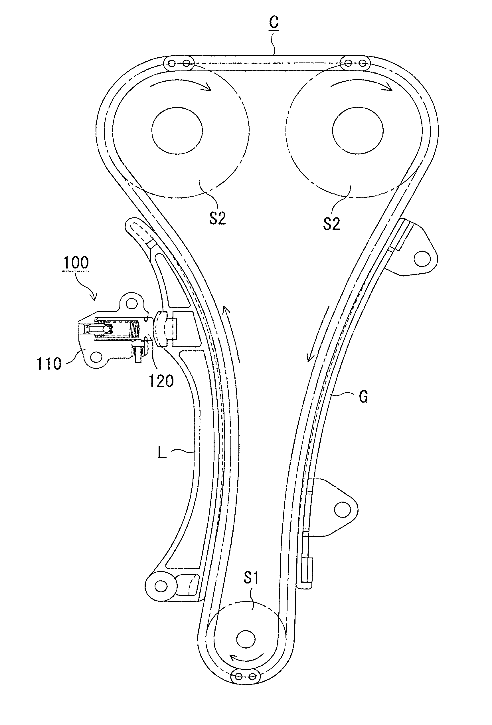
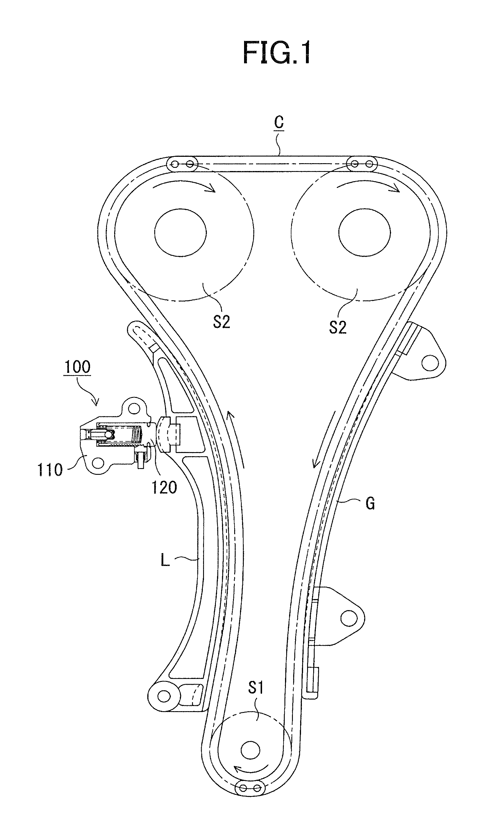
[0025]As shown in FIG. 1, a ratchet-type tensioner 100 is attached to an engine block (not shown) on the slack side of a timing chain C driving by a crankshaft sprocket S1 and driving camshaft sprockets S2. A plunger 120, protruding from the tensioner housing 110, is movable in and out of the tensioner housing toward the chain, and applies tension to the slack side of the chain through a lever L pivotably supported on the engine block by pressing the back of the lever at a location remote from the lever's pivot axis.

[0026]A stationary guide G for guiding the travel of the timing chain is fixed to the engine block on the tension side of the chain.

[0027]The chain transmits rotation from sprocket Si to sprockets S2, and the directions of the sprocket rotation and chain travel are indicated in FIG. 1 by arrows.

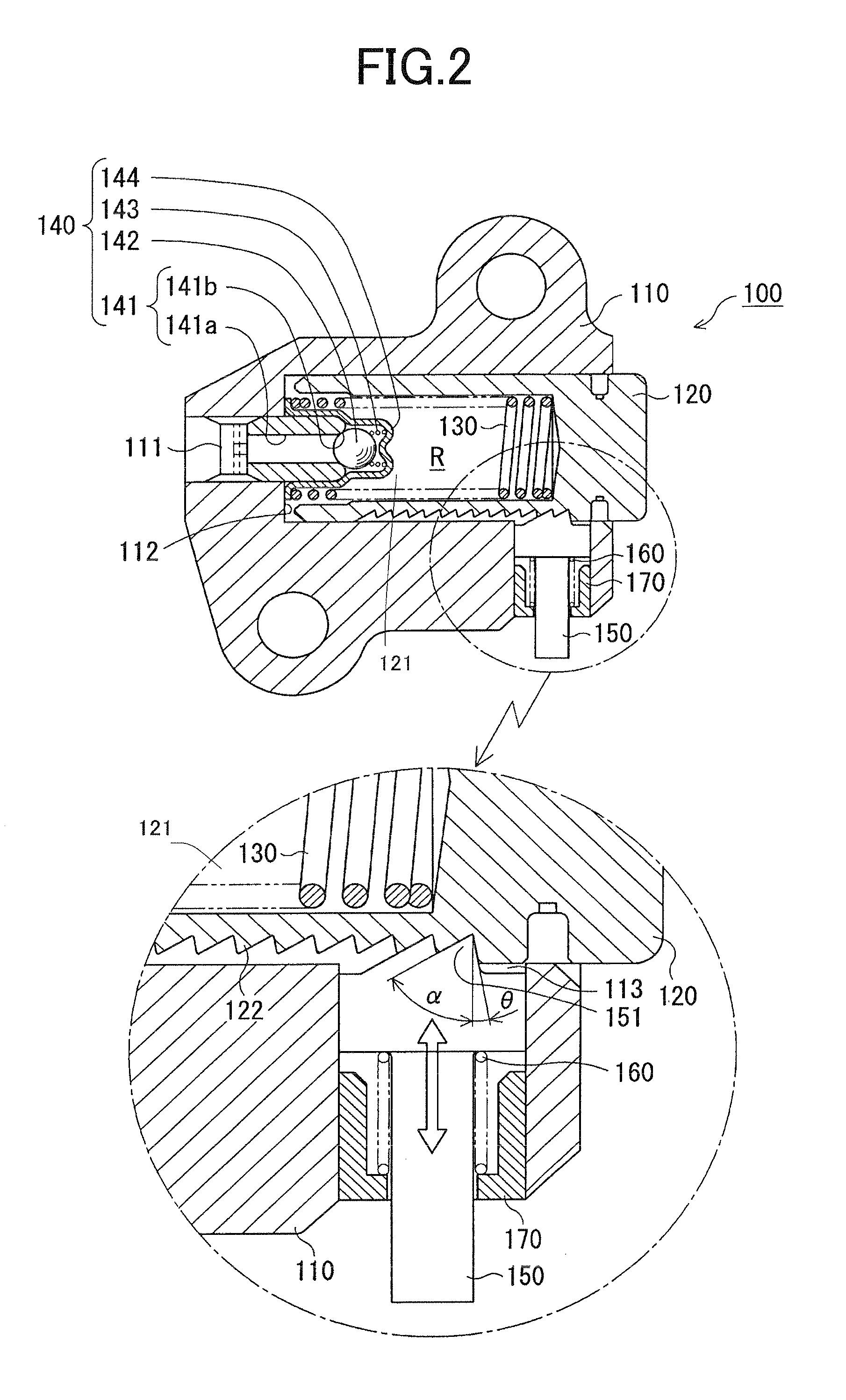
[0028]As shown in FIG. 2, tensioner 100 has a housing 110 having an oil supply passage 111 for introducing oil under pressure from an external supply, usually through a port in th...


PUM


Abstract

In a ratchet-type tensioner having a toothed ratchet piston biased toward a rack of teeth formed on a protruding plunger in a direction transverse to the direction of plunger movement, the rack teeth and the ratchet teeth are mutually engageable and inclined at angles such that the biasing force urging the teeth of the ratchet piston into engagement with the rack teeth is sufficient to block retraction of the plunger during engine start-up but can be overcome when chain tension becomes excessive during engine operation following engine start-up.

Description

CROSS REFERENCE TO RELATED APPLICATIONS[0001]This application claims priority on the basis of Japanese patent application 2010-017098, filed on Jan. 28, 2010. The disclosure of Japanese Patent application 2010-017098 is herein incorporated by reference.FIELD OF THE INVENTION[0002]The invention relates to a ratchet-type tensioner for maintaining tension in the timing chain of an internal combustion engine.BACKGROUND OF THE INVENTION[0003]A conventional hydraulic timing chain tensioner comprises a reciprocating plunger slidable in, and protruding from, a plunger-accommodating hole in a tensioner housing. The plunger and its housing form a high pressure oil chamber that receives oil under pressure from an engine oil pump. The plunger is biased in its protruding direction by a coil spring within the high pressure oil chamber. The spring and the oil pressure cooperatively exert a tensioning force to the timing chain. In a ratchet-type hydraulic tensioner, a ratchet mechanism can be provi...

Claims


Application Information

Patent Timeline
Patent Type & Authority Applications(United States)
IPC IPC(8): F16H7/08
CPCF16H7/0848F16H2007/0806F16H2007/0859F16H2007/0853F16H2007/0812F16H7/08F16H7/18
Inventor KUREMATSU, YUJIHIRAYAMA, MANABU
Owner TSUBAKIMOTO CHAIN CO
Why Eureka
Try Eureka