System stabilizing device

Active Publication Date: 2011-07-28
MEIDENSHA ELECTRIC MFG CO LTD
View PDF1 Cites 4 Cited by
  • Summary
  • Abstract
  • Description
  • Claims
  • Application Information

AI Technical Summary

Benefits of technology

[0080]According to the present invention, in determining the effective current command, redundancy of computation, i.e., the “integral” computation, followed by the “differential” computation, for restoring the initial state, is eliminated. Consequently, the hardware configuration can be downsized, and the computation load can be reduced. Simultaneously, computation by polar coordinate transformation can be cut down.
[0081]Further, in digitizing control (concretely, in exercising control by software processing u

Problems solved by technology

Power generation utilizing natural energy such as sunlight or wind power is generally susceptible to environmental influence, and the amount of power generation fluctuates greatly.
However, governor control is slow in response.
Thus, if electric power consumed by the load 12 suddenly changes, the internal combustion engine type power generation equipment cannot follow such a sudden change (sudden excess or deficiency) in electric power.
When the power load sharply increases at this time, the torque of the generator becomes insufficient for the load power, so that the number

Method used


Image

  • System stabilizing device
  • System stabilizing device
  • System stabilizing device

Examples


embodiment 1

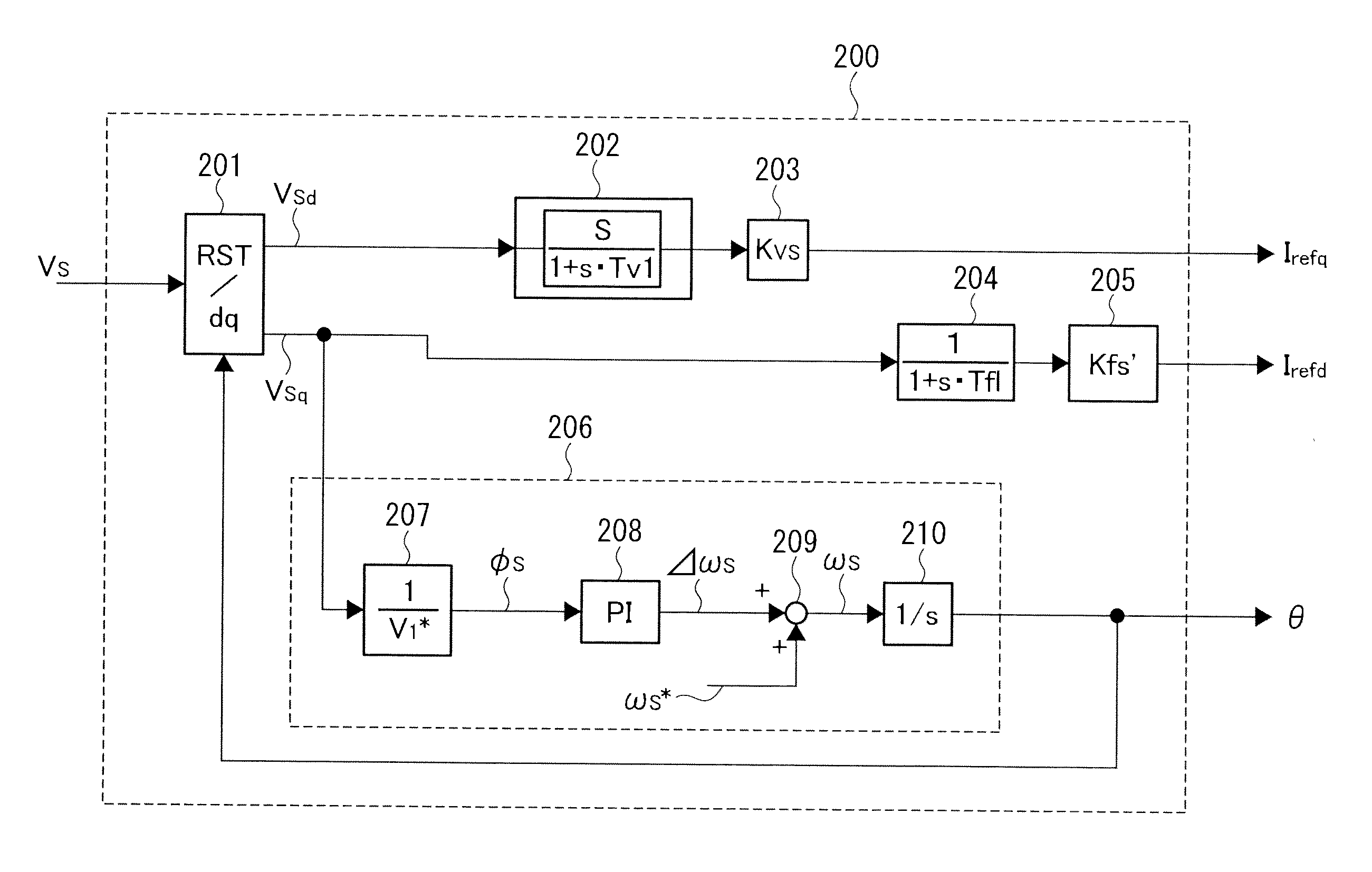
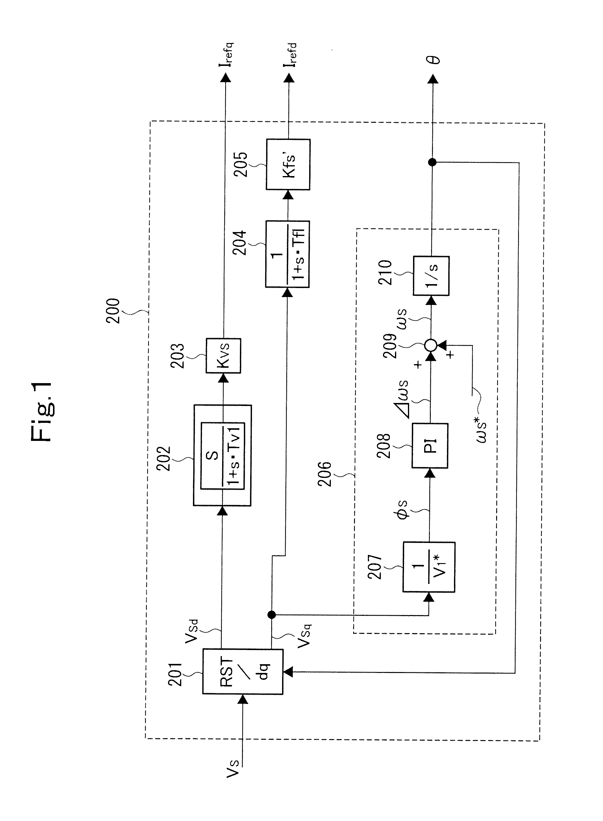
[0088]FIG. 1 shows a self-supporting control unit 200 according to the embodiment of the present invention. The self-supporting control unit 200 is used instead of the self-supporting control unit 21 in the system stabilizing device 20 shown in FIG. 4.

[0089]As shown in FIG. 1, a dq transforming unit 201 of the self-supporting control unit 200 dq-transforms the three-phase system voltage Vs to output an effective system voltage Vsd and an ineffective system voltage Vsq of a rotating coordinate system. A fluctuation detecting unit 202 is a filter having differential characteristics and first-order lag characteristics, and outputs the fluctuation component of the effective system voltage Vsd. This fluctuation component is multiplied by a predetermined gain by a proportional computing unit 203 to determine an ineffective current command Irefq.

[0090]When a PLL action by a PLL circuit 206 to be described later is performed, the voltage amplitude signal |Vs| in a steady state is nearly equ...


PUM


Abstract

A system stabilizing device disposed in a micro grid incorporates a self-supporting control unit (200). The self-supporting control unit (200) allows a dq transforming unit (201) to determine an effective system voltage Vsd and an ineffective system voltage Vsq from a system voltage Vs. A fluctuation detecting unit (202) has differential characteristics and first-order lag characteristics, and determines the fluctuation component of the effective system voltage Vsd. This fluctuation component is multiplied by a gain in a proportional computing unit (203) to determine an ineffective current command Irefq. A fluctuation detecting unit (204) does not have differential characteristics, but has first-order lag characteristics, and determines the fluctuation component of the ineffective system voltage Vsq. This fluctuation component is multiplied by a gain in a proportional computing unit (205) to determine an effective current command Irefd. By so doing, hardware and computation load necessary for system stabilizing control during a self-supporting run can be reduced in the system stabilizing device.

Description

TECHNICAL FIELD[0001]This invention relates to a system stabilizing device, and is designed to reduce hardware and operation or computation load which are necessary for system stabilizing control during an isolated or self-supporting operation or run.BACKGROUND ART[0002]Power generation utilizing natural energy such as sunlight or wind power is generally susceptible to environmental influence, and the amount of power generation fluctuates greatly. A system stabilizing device is used for the purpose of accommodating or absorbing this fluctuation.[0003]In a micro grid having a network constructed by installing a power source, such as natural energy, near the electric power demand side, the installation of a system stabilizing device, which keeps demand for and supply of electric power in balance, is necessary for system stabilization.[0004]An example of the micro grid (electric distribution or distribution system) equipped with a system stabilizing device will be described by referenc...

Claims


Application Information

Patent Timeline
IPC IPC(8): G06F1/26
CPCG05B5/01H02J3/38H02J3/32Y02P80/14
Inventor OI, KAZUNOBUMUNESHIMA, MASAKAZUHIRAYAMA, ISSEI
Owner MEIDENSHA ELECTRIC MFG CO LTD
Why Eureka
Try Eureka