Fuel heater system including hot and warm water sources

a technology of hot and warm water and fuel heater, which is applied in the direction of turbine/propulsion fuel heating, lighting and heating apparatus, machines/engines, etc., can solve the problems of fuel being delivered at inappropriate preheated temperatures, damage to the combustor, and delay in controlling the preheated temperatur

Active Publication Date: 2011-08-04
GENERAL ELECTRIC CO
View PDF11 Cites 28 Cited by
  • Summary
  • Abstract
  • Description
  • Claims
  • Application Information

AI Technical Summary

Problems solved by technology

However, a conventional fuel delivery system may have limitations that result in difficulties or delays in controlling the preheated temperature of fuel as it is delivered to the combustor.
This may lead to the fuel being delivered at inappropriate preheated temperatures.
However, given limitations of conventi...

Method used


Image

  • Fuel heater system including hot and warm water sources
  • Fuel heater system including hot and warm water sources
  • Fuel heater system including hot and warm water sources

Examples


Embodiment Construction

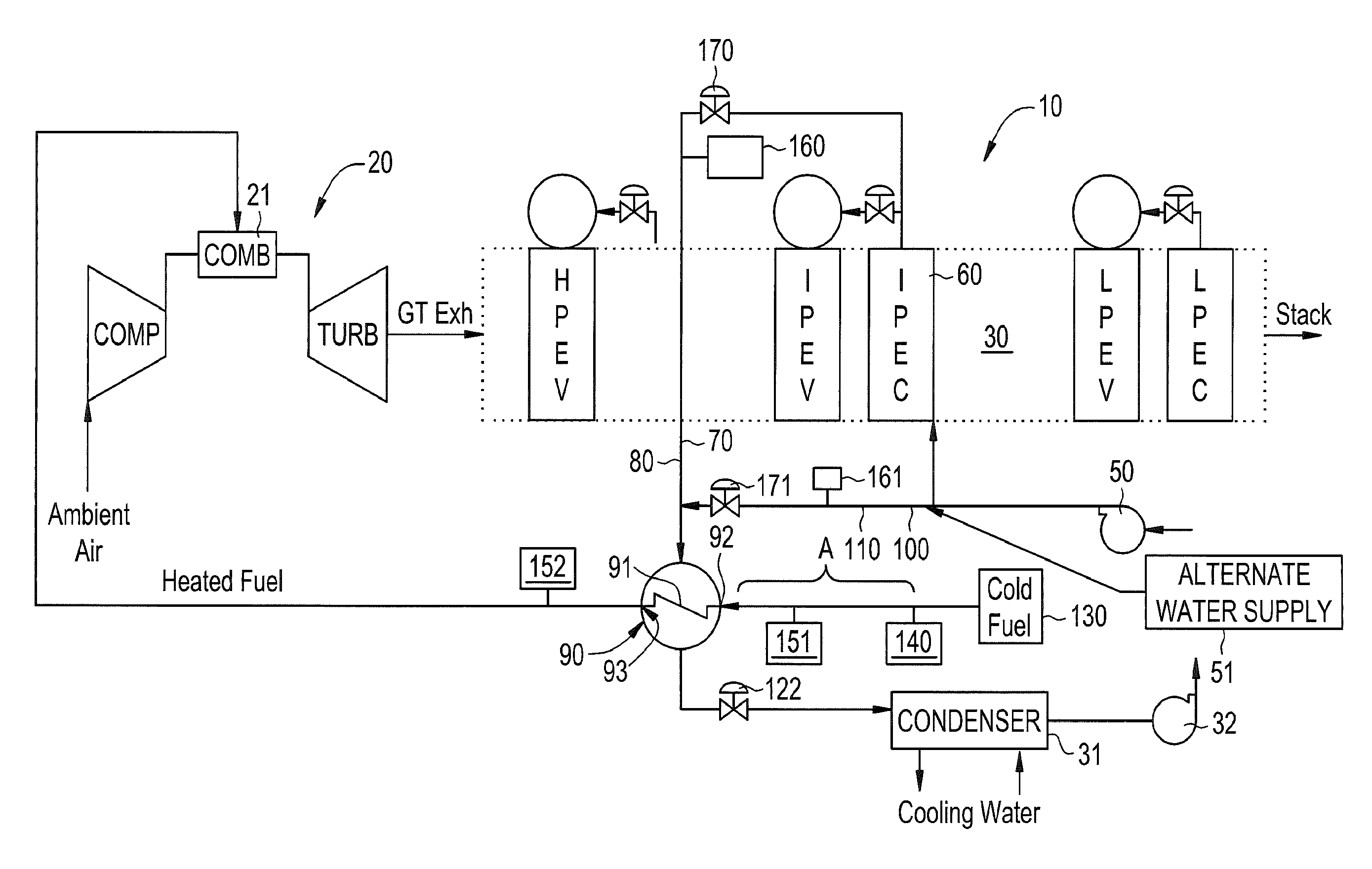
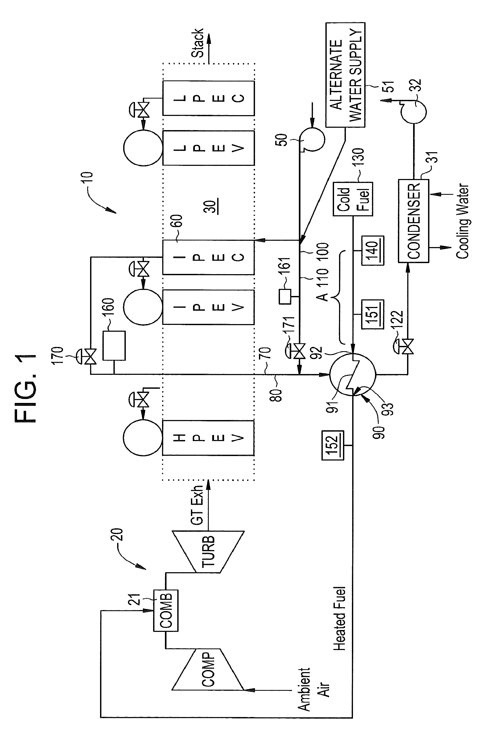
[0017]With reference to FIGS. 1-3, in a combined cycle power plant 10, fuel and air are combusted in a gas turbine engine 20 to generate mechanical energy, heat energy and electricity. A portion of the heat energy is transmitted to a Heat Recovery Steam Generator (HRSG) 30 where the heat energy is employed to generate steam from, for example, water condensed in a condenser 31 and pumped by a condensate pump 32. A portion of the steam is then used to generate additional mechanical energy and / or electricity.

[0018]In accordance with exemplary embodiments, water recycled from the HRSG 30 may be directed to a feed water pump 50, which pumps a portion of the recycled water to, for example, an IP economizer 60 of the HRSG 30. This water is heated and output at a temperature of approximately 440° F. as a first water supply 70. This first water supply 70 of relatively hot water is then supplied via first piping 80 toward a heat exchanger 90 where it can be employed to heat fuel flowing to a ...


PUM


Abstract

A system is provided and includes first and second water supplies at first and second relatively high and low temperatures, respectively, a heat exchanger, coupled to the water supplies, through which fuel and relative amounts of the water supplies at the first and second temperatures flow for fuel heating and a controller, operably interposed between the water supplies and the heat exchanger, to select and/or modulate the relative amounts of the water supplies permitted to flow through the heat exchanger to heat the fuel to a temperature based on a heating requirement to meet a modified wobbe index (MWI) rating.

Description

BACKGROUND OF THE INVENTION[0001]The subject matter disclosed herein relates to fuel heating system using hot and warm water sources.[0002]In general, gas turbine engines include a compressor, a combustor, and a turbine. The compressor and turbine generally include rows of blades that are axially stacked in stages. Each stage includes a row of circumferentially-spaced stator blades, which are fixed, and a row of rotor blades, which rotate about a central axis or shaft. In operation, the compressor rotor blades rotate about the shaft, and, acting in concert with the stator blades, compress a flow of air. The supply of compressed air then is used in the combustor to combust a supply of fuel. The resulting flow of hot gases from the combustion is expanded through the turbine and causes the turbine blades to rotate such that the system as a whole acts to convert fuel into mechanical energy.[0003]Often, the supply of fuel used in a combustor is preheated to promote efficient engine opera...

Claims


Application Information

Patent Timeline
IPC IPC(8): F02C9/26
CPCF02C9/26Y02E20/16F02C7/224F23N2221/10F02C9/40F02C6/18
Inventor BILTON, TIMOTHY RUSSELLERICKSON, DEAN MATTHEWGALLAGHER, BRIAN MICHAELELURIPATI, RAVI PRAVEENSIVASANKARAN, RAKESH
Owner GENERAL ELECTRIC CO
Why Eureka
Try Eureka