Detection of deposits in flowlines

a flowline and deposit technology, applied in the direction of instruments, vibration measurement in solids, specific gravity measurement, etc., can solve the problems of affecting the flow rate of the lin

Active Publication Date: 2011-08-04
SCHLUMBERGER TECH CORP
View PDF21 Cites 34 Cited by
  • Summary
  • Abstract
  • Description
  • Claims
  • Application Information

AI Technical Summary

Benefits of technology

[0007]It is an object of the present invention to provide an imp...

Problems solved by technology

However, producing oil and gas from floating production platforms (FPSO) presents many challenges which increase as the water depth increases.
However, because the temperature of the fluid in the flowline can change as flow conditions change, waxes or hydrates can deposit on the inside of the flowlines.
In particular, when production is stopped, the temperature of the fluid in the line will decrease as a result of heat loss to the surrounding, cooler sea water.
These are not always well known and so unexpected deposition may occu...

Method used


Image

  • Detection of deposits in flowlines
  • Detection of deposits in flowlines
  • Detection of deposits in flowlines

Examples


Embodiment Construction

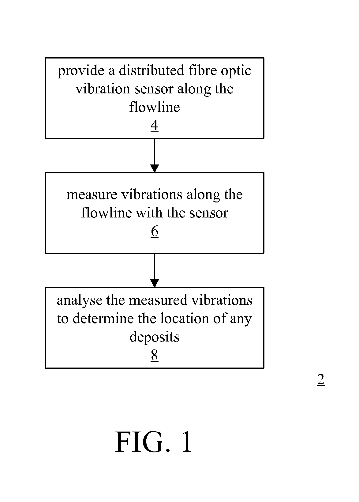
[0020]Referring to FIG. 1, an embodiment of the invention provides a method 2 of determining the location of deposits in a flowline. The method 2 comprises: providing 4 a distributed vibration sensor along the flowline; measuring $ vibrations along the flowline with the sensor; and analysing 8 the measured vibrations to determine the location of any deposits.

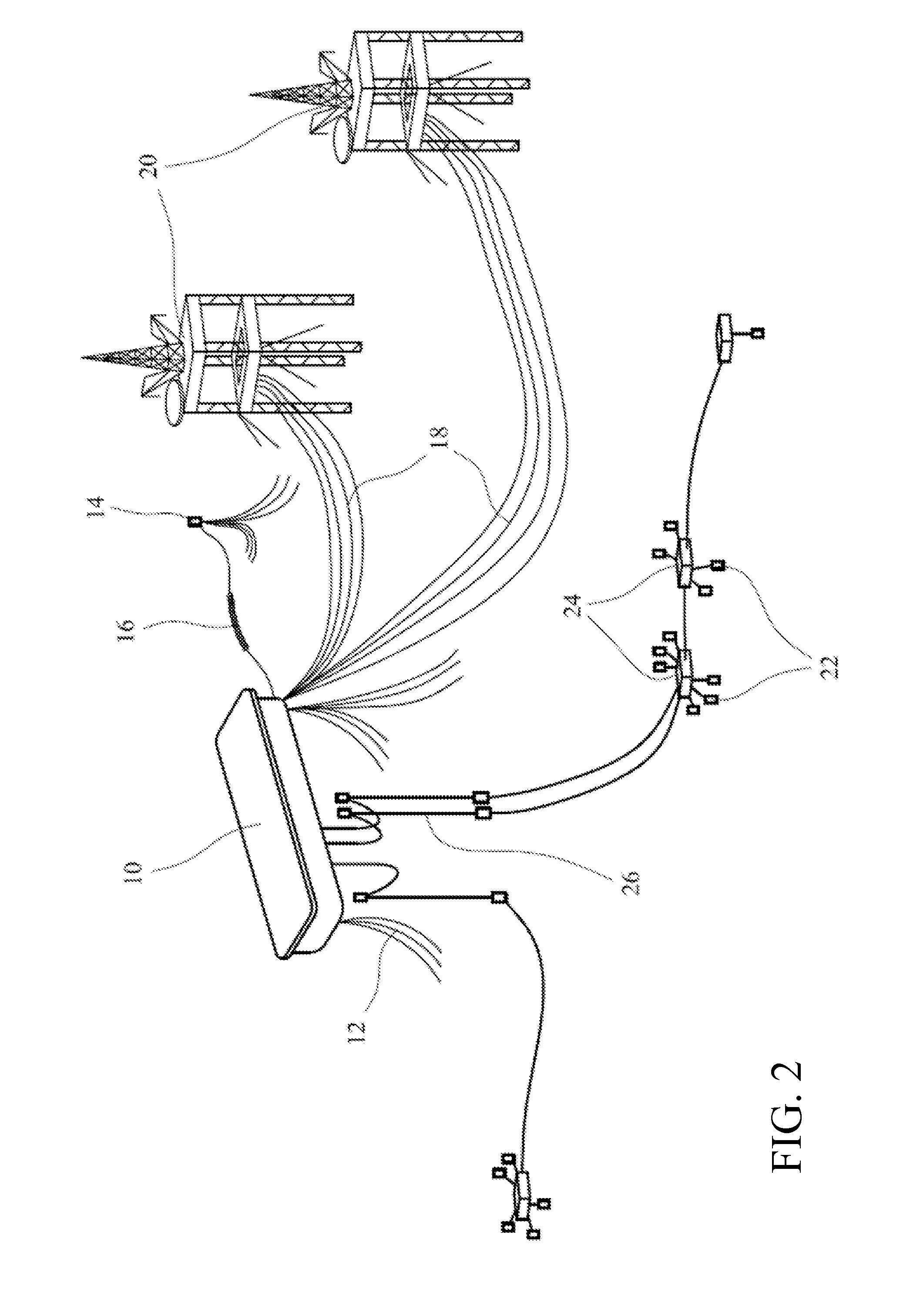
[0021]The method 2 is particularly applicable to monitoring subsea installations in the oil and gas industry. Referring to FIG. 2 of the drawings, there is shown a schematic illustration of a subsea system comprising a floating production platform (FPSO) vessel 10 which is anchored to the sea bed by anchor chains 12. A tanker offloading buoy 14 is connected to the FPSO 12 by means of a flexible offloading pipeline 16. Further flexible flowlines 18 connect the FPSO 10 to nearby platforms 20 to allow direct production of oil and gas to the FPSO. Also, existing subsea wells 22 have connections to subsea manifolds 24 from which flex...


PUM


Abstract

A method 2 of determining the location of deposits in a flowline comprises providing 4 a distributed vibration sensor along the flowline, measuring 6 vibrations along the flowline with the sensor and analysing 8 the measured vibrations to determine the location of any deposits. The vibration measurements are made using a distributed fibre optic sensor provided on the flowline. The measurements are analysed in real time to identify deposit formation and location within the flowline.

Description

TECHNICAL FIELD[0001]The present invention relates to a method of determining the location of deposits in flowlines in the oil and gas industry and particularly, but not exclusively to a technique that can be used in real time or quasi-real time.BACKGROUND ART[0002]Subsea production of oil and gas is projected to increase significantly in the next 5-10 years. However, producing oil and gas from floating production platforms (FPSO) presents many challenges which increase as the water depth increases. The fluids produced from the wellheads on the seabed are typically transferred to the FPSO through flexible flowlines (also known as risers or pipelines). However, because the temperature of the fluid in the flowline can change as flow conditions change, waxes or hydrates can deposit on the inside of the flowlines. In particular, when production is stopped, the temperature of the fluid in the line will decrease as a result of heat loss to the surrounding, cooler sea water. The fluid cond...

Claims


Application Information

Patent Timeline
IPC IPC(8): G01H9/00G01H11/00
CPCG01H9/004
Inventor MCCANN, DOMINIC
Owner SCHLUMBERGER TECH CORP
Why Eureka
Try Eureka