Heat exchanger for the outer skin of an aircraft

a technology of heat exchanger and aircraft, which is applied in the direction of energy-saving board measures, lighting and heating apparatus, laminated elements, etc., can solve the problems of low current consumption, low air resistance, and low installation space requirements, so as to facilitate and improve the cooling through the heat transfer device and improve the cooling power

Active Publication Date: 2011-08-04
AIRBUS OPERATIONS GMBH
View PDF38 Cites 35 Cited by
  • Summary
  • Abstract
  • Description
  • Claims
  • Application Information

AI Technical Summary

Benefits of technology

[0022]In an advantageous improvement of the heat transfer device the coolant ducts are realised as gaps between a heat receiving plate and a pressure bulkhead and/or an outer kin of the aircraft. This facilitates and improves the cooling through the heat transfer device according to the invention, since the use of airfrom the surroundings of the aircraft or from the passenger cabin is particularly easy. The invention is not limited to the use of a single plate, in fact larger stacks of plates with air gaps or the s...

Problems solved by technology

These are, in particular, the least-possible (additional) air resistance, low cu...

Method used


Image

  • Heat exchanger for the outer skin of an aircraft
  • Heat exchanger for the outer skin of an aircraft
  • Heat exchanger for the outer skin of an aircraft

Examples


Embodiment Construction

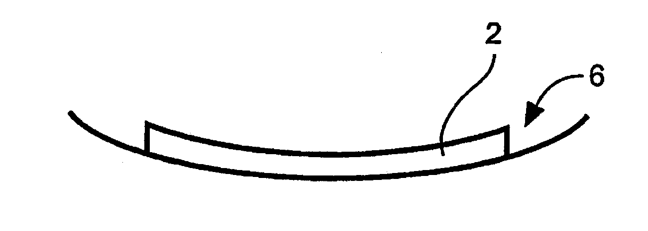
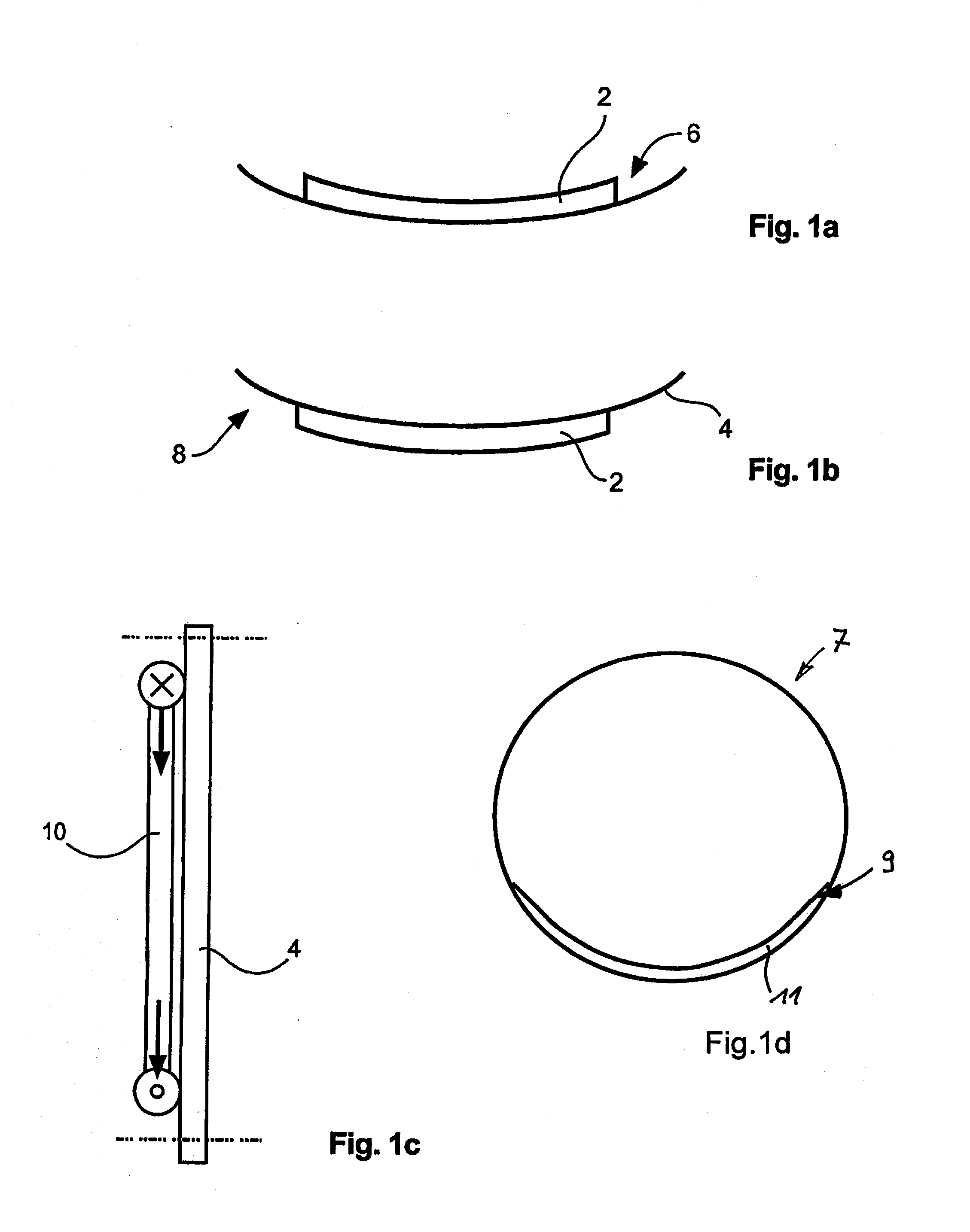
[0041]FIG. 1a generally shows the manner in which a heat transfer device 2 can be arranged on the outer skin 4 of an aircraft. In this embodiment the heat transfer device 2 is arranged on the interior 6 of the aircraft, whereas in the embodiment of FIG. 1b the heat transfer device 2 is positioned on the exterior 8 of the aircraft. In these different installation positions it should be noted that the heat transfer device 2 has to meet different mechanical requirements. If the heat transfer device 2 is arranged on the interior 6 of the aircraft, in particular cases the heat transfer device 2 must be designed to absorb structural loads acting on the fuselage. In the case of relatively large-area heat transfer devices 2, which is not unrealistic in view of large quantities of heat without active cooling units, for flush installation of the heat transfer device 2 to the outer skin 4, in some regions the fuselage structure which exists in those locations and that comprises frame elements,...


PUM


Abstract

A heat exchanger for an outer skin of an aircraft comprises at least one feed line for a coolant, at least one discharge line for the coolant and at least one bundle of coolant channels through which coolant flows, wherein in the case of the heat exchanger being attached to the outer skin, the coolant channels are positioned directly on the outer skin of the aircraft, at least in areas, for dissipating heat to the surrounding environment of the aircraft. The heat exchanger may comprise cooling fins around which air flows for increasing the heat dissipation.

Description

RELATED APPLICATIONS[0001]This application claims the benefit of the filing date of U.S. Provisional Patent Application No. 61 / 137,472, filed Jul. 31, 2008 and of German Patent Application No. 10 2008 035 823.1, filed Jul. 31, 2008, the disclosure of which applications is hereby incorporated herein by reference.TECHNICAL FIELD[0002]The invention relates to a heat transfer device for the outer skin of an aircraft, to a cooling system for an aircraft, to a use of a heat transfer device for the outer skin of an aircraft, as well as to an aircraft comprising at least one heat transfer device for the outer skin.BACKGROUND OF THE INVENTION[0003]In modern commercial aircraft there are various components that have certain cooling requirements. For example, environmental control systems require the supply or production of a cool medium in order to provide the best possible thermal comfort for passengers on board the aircraft, whereas, for example, a host of electronic devices and installatio...

Claims


Application Information

Patent Timeline
IPC IPC(8): F28F7/00
CPCB64D13/00Y02T50/44F28D2021/0021F28F3/12F28F1/00Y02T50/56Y02T50/50Y02T50/40B64D2013/0607B64D13/06
Inventor PIESKER, MARKUS
Owner AIRBUS OPERATIONS GMBH
Why Eureka
Try Eureka