
Method and magnetic resonance system to reduce distortions in diffusion imaging

a magnetic resonance system and imaging technology, applied in the field of magnetic resonance system to reduce can solve the problems of image distortions having an appearance, incorrect association of pixel information, errors (or at to a reduced precision) of calculated parameters, etc., and achieve sufficient robustness and quick effect of reducing distortions in diffusion imaging

Active Publication Date: 2011-08-04
SIEMENS HEALTHCARE GMBH
View PDF8 Cites 25 Cited by
  • Summary
  • Abstract
  • Description
  • Claims
  • Application Information

AI Technical Summary

Benefits of technology

[0013]An object of the present invention is to provide an improved method to reduce distortions in diffusion imaging, which method also takes interference fields with more complex spatial geometry into account in the correction and is nevertheless sufficiently robust and quick. A further object is to provide a magnetic resonance system that is designed to implement a more complex spatial geometry within the scope of the invention is an interference field geometry that goes beyond an affine transformation.
[0019]The method according to the invention or, respectively, the magnetic resonance system according to the invention has the advantage that on the on hand not only affine transformations but also significantly more complex geometries of the interference fields can be taken into account. On the other hand, however, the use of a system-specific distortion correcting function provides that the number of correction parameters to be determined keeps within a scope in which a robust and fast determination of the correction parameters is still possible. The distortion correcting function is additionally better adapted to the actual existing interference conditions than in previous methods, and therefore can lead to more precise corrections.
[0027]Since the bandwidth is typically greater by a factor of 100 in the readout direction r than in the phase coding direction p, normally no relevant distortion occurs in the readout direction r in relationship to the phase coding direction p. Therefore a correction of the magnetic resonance images also preferably takes place only in the phase coding direction. This has the advantage that only this direction must be taken into account in the determination of the correction parameters, and thus the number of correction parameters to be determined is lower, whereby significant computing effort can be spared in the determination of the correction parameters and in the later correction with application of the correction parameters.
[0035]In a preferred variant, the test image pixels are selected so that they lie within an image region selected under consideration of the image content. The relevance of the transformation is then ultimately determined depending on the image content. For example, for this in which region of the image the significant information lies can initially be determined with a typical image evaluation method. This image region can have an irregular shape. However, an (advantageously rectangular) image section comprising the region of interest could particularly preferably be determined as a “bounding box”. Only pixels in this image region are then considered in the evaluation of the relevance of the transformations. In addition to the improved identification of the relevant transformations or, respectively, the associated polynomial elements, the processing speed is markedly increased with this approach, and at the same time the precision of the similarity comparison can be improved given use of a similarity function for iterative determination of the correction parameters.
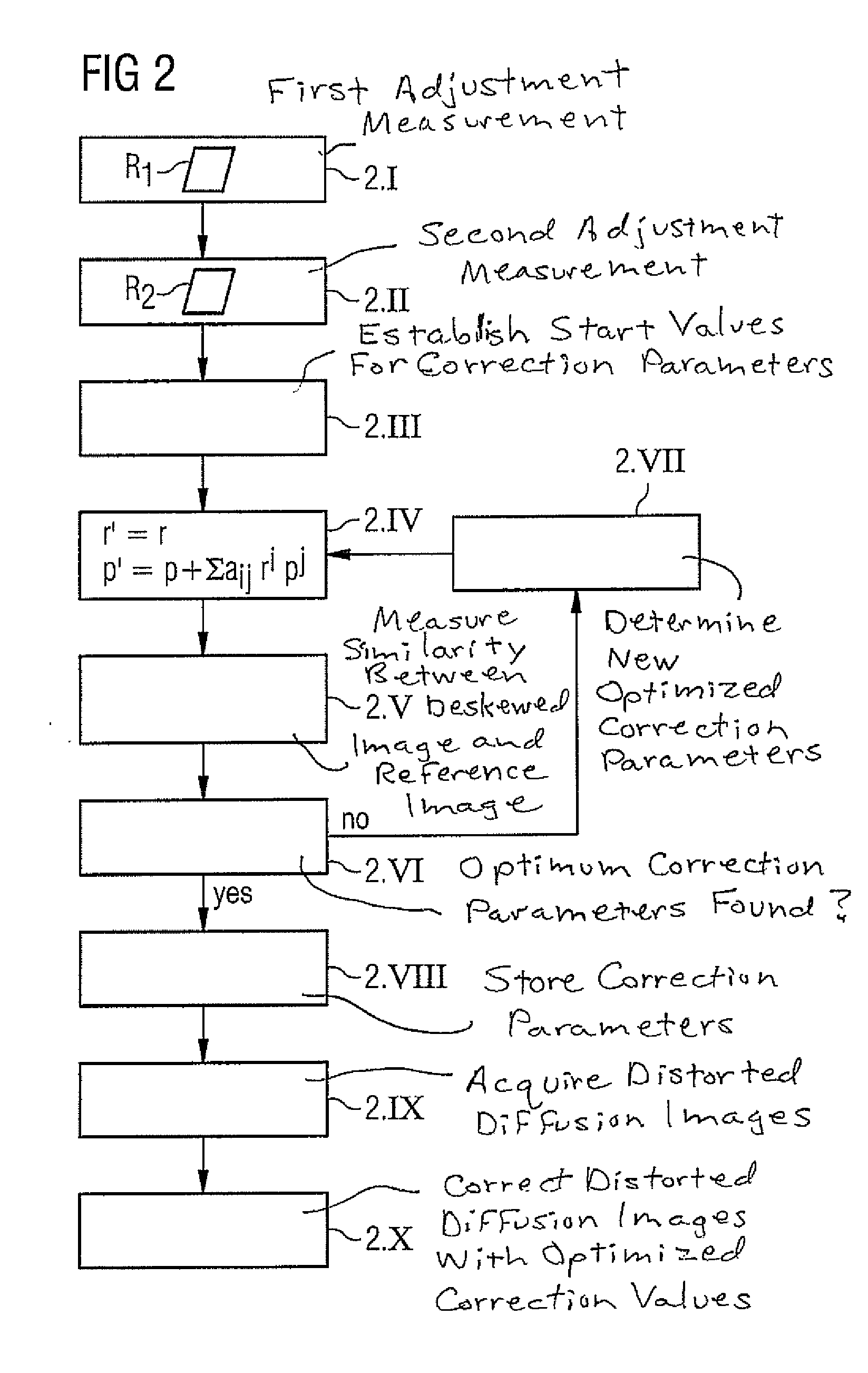
[0037]In spite of consideration of non-affine transformations, with the method explained above the number of transformation parameters is held within limits and a robust method to discover optimal correction parameters is thus enabled. In order to improve the robustness of the method even further—in particular in the cases in which the number of polynomial elements in the distortion correcting function (and thus the number of correction parameters) should reasonably be chosen somewhat higher due to the relevance of the transformations—in a particularly preferred development of the method a hierarchical (cluster) search can be used in an iterative determination of the correction parameters. One possible method for this is explained later in an exemplary embodiment.

Problems solved by technology

Eddy current fields can disadvantageously be caused by the diffusion gradients, these eddy current fields in turn leading to image distortions having an appearance that depends both on the amplitude of the gradients (i.e. the diffusion weighting) and on their direction.
If the acquired individual images are then combined with one another with no correction in order to generate (for example) the cited parameter maps, the distortions, which are different for every image, lead to incorrect associations of pixel information and therefore to errors (or at to a reduced precision) of the calculated parameters.
Particularly in diffusion-weighted images that were acquired with the use of the echoplanar technique (EPI), eddy current-dependent distortions represent a particularly significant challenge, since a particularly high sensitivity (approximately 10 Hz per pixel in the phase coding direction) to static and dynamic field interference typically exists in EPI imaging, and high gradient amplitudes are specifically used here to adjust the diffusion gradients.
However, in modern MR systems this assumption is not always correct.
It is a problem that the correction method takes longer the more complex the geometry that is to be taken into account in the distortion correction, since the computational effort for correction rises dramatically with the increasing number of parameters to be taken into account.
The use of all possible field geometries up to the 2nd order as occurs in the method by Rohde et al., already leads to a relatively high computational cost.

Method used


Image

  • Method and magnetic resonance system to reduce distortions in diffusion imaging
  • Method and magnetic resonance system to reduce distortions in diffusion imaging
  • Method and magnetic resonance system to reduce distortions in diffusion imaging

Examples


Embodiment Construction

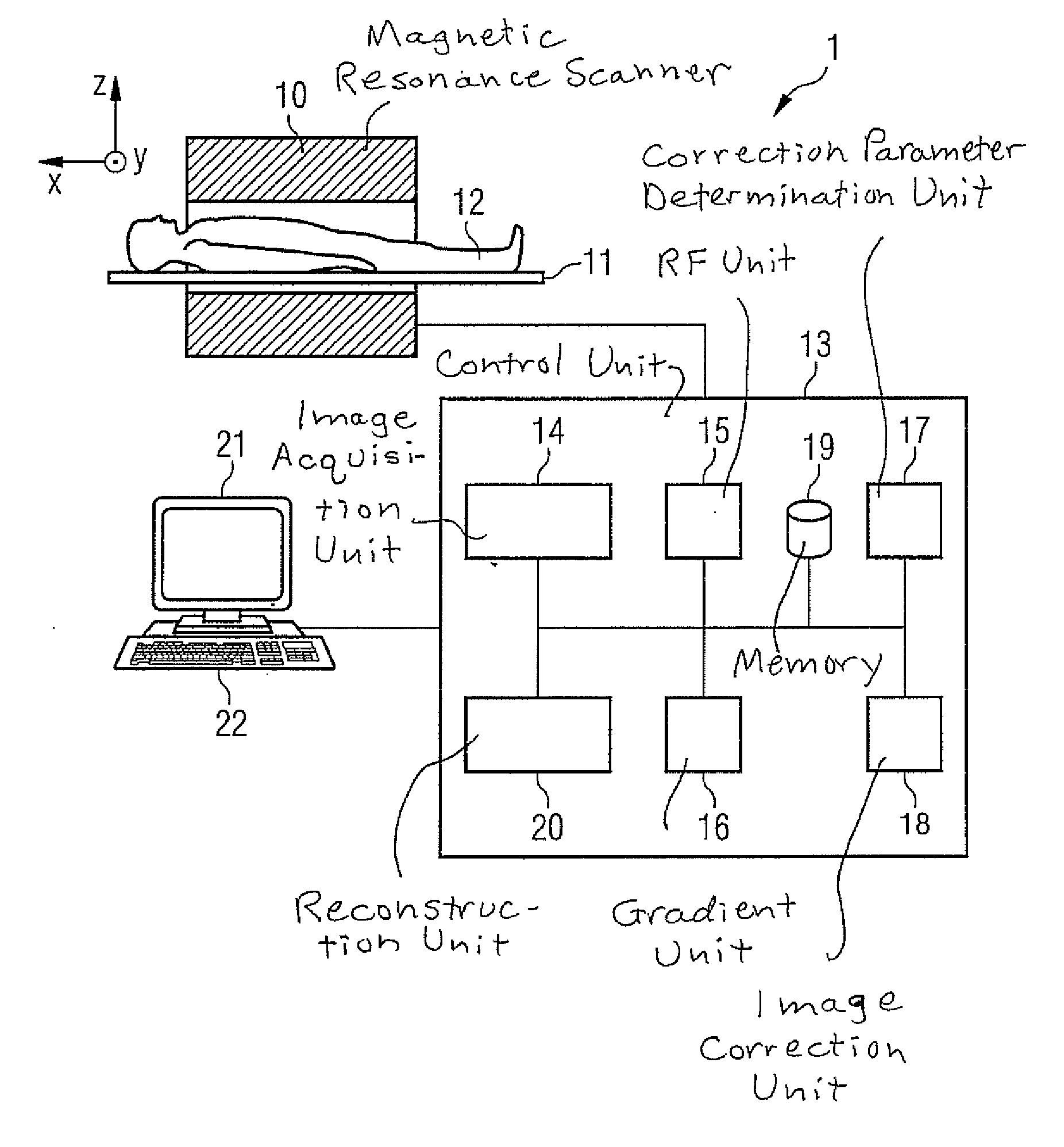
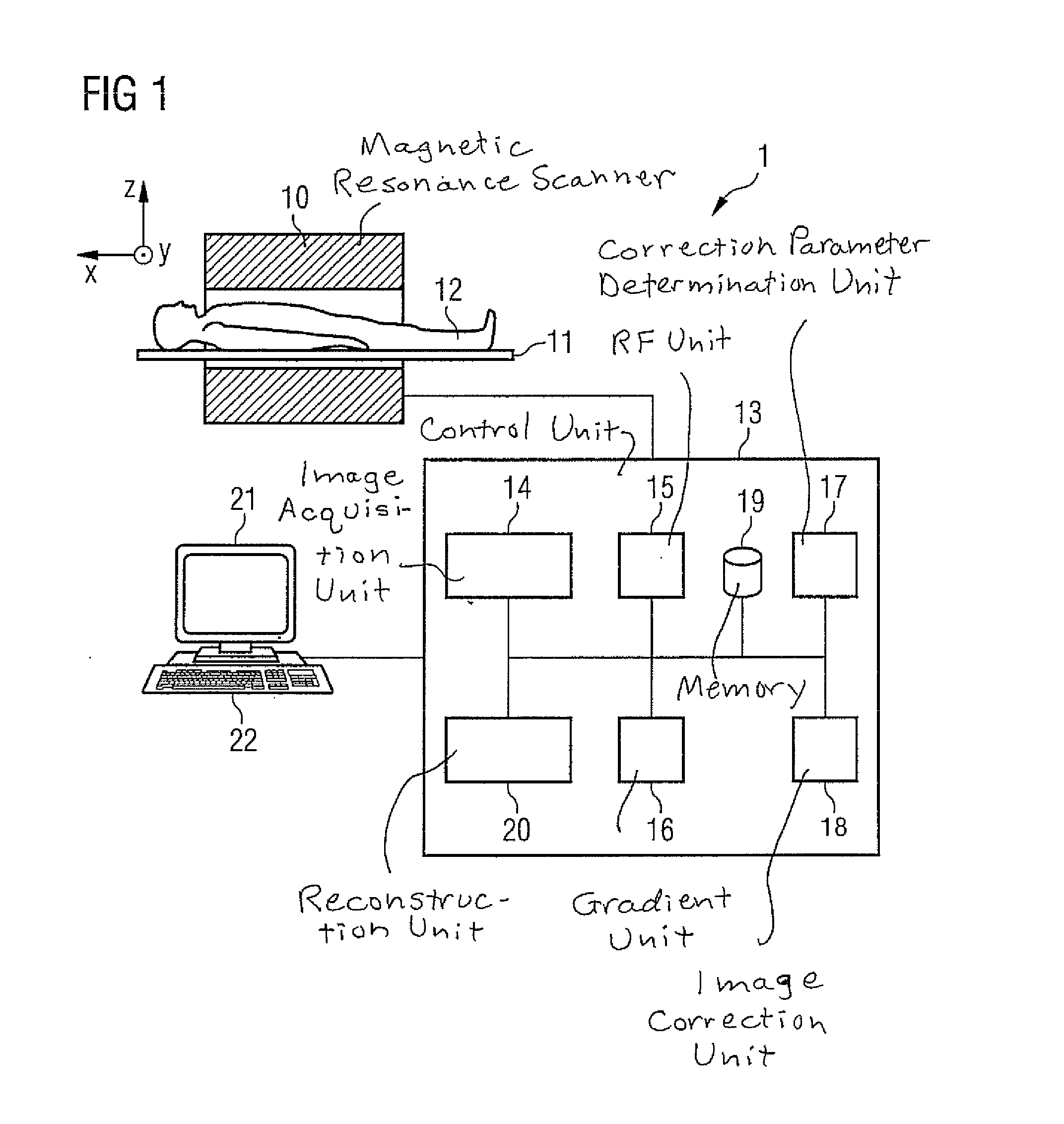
[0046]A magnetic resonance system 1 according to the invention is presented in a rough schematic in FIG. 1. It includes the actual magnetic resonance scanner 10 with an examination space or patient tunnel into which an examination subject 12 on a bed 11 can be driven. The magnetic resonance scanner 10 is equipped in a typical manner with a basic field magnet system, a gradient coil system and a transmission and reception antenna system which, for example, includes a whole-body coil permanently installed in the magnetic resonance scanner 10 and possible additional local coils that can be variably arranged on the examination subject 12.

[0047]The MR system 1 furthermore has a central control unit 13 that is used to control the entire MR system 1. The central control unit 13 has an image acquisition unit 14 for pulse sequence control. In this the sequence of RF pulses and gradient pulses is controlled depending on a selected imaging sequence. The central control unit 13 has an RF unit 1...


PUM


Abstract

In a method and magnetic resonance apparatus to reduce distortions in magnetic resonance diffusion imaging, a magnetic resonance data acquisition system is operated to acquire magnetic resonance data in a first measurement with a first diffusion weighting, and to acquire magnetic resonance data in a second measurement with a second, different diffusion weighting. A non-linear, system-specific distortion-correcting function is determined on the basis of system-specific information that is specific to said magnetic resonance data acquisition system. Correction parameters are calculated to correct distortions in subsequently-acquired diffusion-weighted magnetic resonance images, based on the data acquired in the first and second measurements with the system-specific distortion-correcting function applied thereto. The subsequently-acquired diffusion-weighted magnetic resonance images are corrected using the correction parameters to at least reduce distortions therein.

Description

BACKGROUND OF THE INVENTION[0001]1. Field of the Invention[0002]The present invention concerns a method to correct image distortions that can occur upon acquisition of diffusion-weighted magnetic resonance (MR) images of an examination subject, as well as a magnetic (MR) resonance system with which such a method can be implemented.[0003]2. Description of the Prior Art[0004]In diffusion imaging, multiple images are normally acquired with different diffusion directions and weightings, and are combined with one another. The strength of the diffusion weighting is usually defined by what is known as the “b-value”. The diffusion images with different diffusion directions and weightings, or the images combined therefrom can then be used for diagnostic purposes. Parameter maps with particular diagnostic significance, for example, maps that reflect the “Apparent Diffusion Coefficient (ADC)” or the “Fractional Anisotropy (FA)”, can be generated by suitable combinations of the acquired, diffus...

Claims


Application Information

Patent Timeline
Patent Type & Authority Applications(United States)
IPC IPC(8): G01R33/44
CPCG01R33/44G01R33/56341G01R33/5616
Inventor FEIWEIER, THORSTENHUWER, STEFANKIM, TONY HYUNPORTER, DAVID ANDREWSPECKNER, THORSTEN
Owner SIEMENS HEALTHCARE GMBH
Learn More