Eureka AIR delivers breakthrough ideas for toughest innovation challenges, trusted by R&D personnel around the world.

Receiver test circuits, systems and methods

Inactive Publication Date: 2011-08-04
INFINEON TECH AG
View PDF19 Cites 2 Cited by
  • Summary
  • Abstract
  • Description
  • Claims
  • Application Information

AI Technical Summary

Benefits of technology

[0006]In an embodiment, a system comprises an integrated circuit comprising a receiver, and a pulse train generator comprising an inverter chain having a gate delay, wherein the pulse train generator is configured to generate a pulse train and apply the pulse train to an input of the receiver and an input of a low pass filter, whe

Problems solved by technology

The former is costly and time inefficient, while the latter provides only a general indication of circuit performance rather than an oft-desired thorough characterization.
While the integration of test signal sources on chip has been proposed, such a solution can be imperfect because the properties of the test signal vary with process variations and are not known exactly.
Therefore, it can be difficult to obtain precise measurements, and a need for accurate and cost-effective testing remains.

Method used


Image

  • Receiver test circuits, systems and methods
  • Receiver test circuits, systems and methods
  • Receiver test circuits, systems and methods

Examples


Embodiment Construction

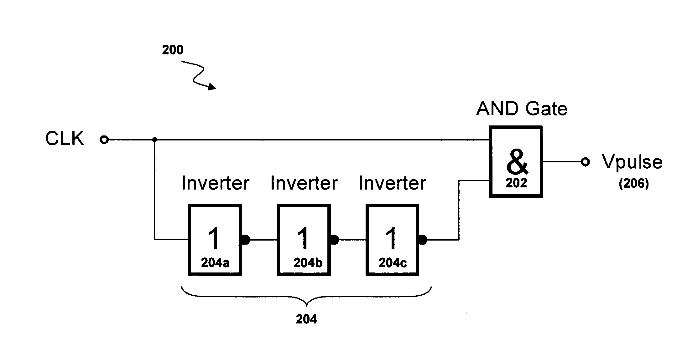
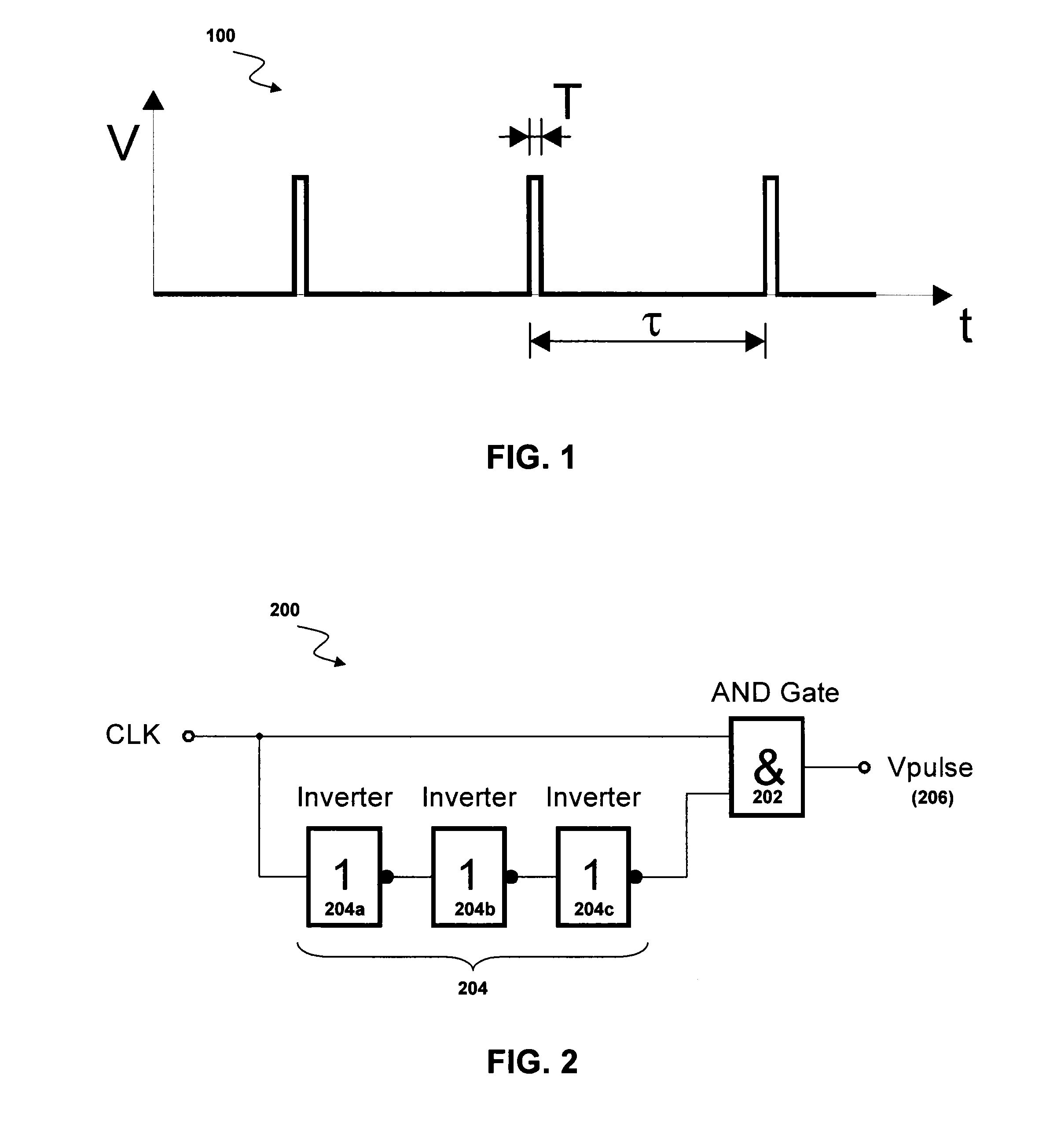
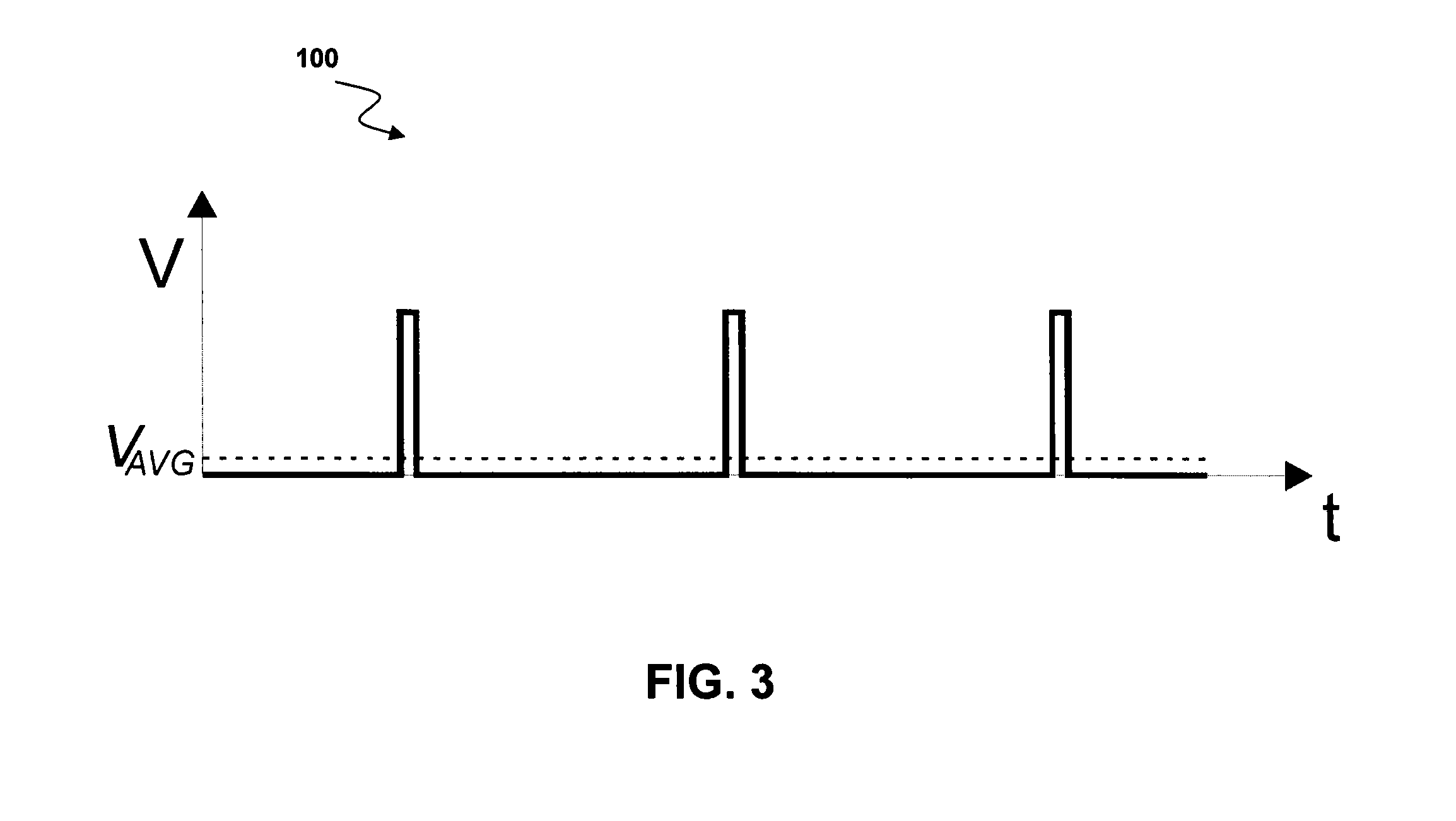
[0018]Embodiments relate to test signal generators and methods for testing high frequency receivers. The test signal generator circuit and the receiver to be tested can be integrated on the same integrated circuit. In an embodiment, the circuit is intended for testing receivers after production, such as in frontend and / or backend test, as well as in the application. A goal is to provide accurate testing of receiver performance at low cost and without the need for expensive test equipment. This is especially pertinent to receivers in the millimeter wave range (e.g., for automotive radar applications that operate at 77 GHz), for which conventional testing requires significant effort. While the examples herein will generally be discussed in the context of radar applications, such as automotive, operating at 77 GHz, other frequencies and / or applications can be used in various embodiments.

[0019]The invention addresses the problems related to testing integrated receivers by generating a w...


PUM


Abstract

Embodiments relate to apparatuses, systems and methods for testing high-frequency receivers. In an embodiment, a method includes integrating a pulse train generator and a receiver in an integrated circuit; generating a pulse train by the pulse train generator and applying the pulse train to an input of the receiver; measuring at least one property of the pulse train; and determining at least one characteristic of the receiver using the at least one property of the pulse train. In an embodiment, an integrated circuit includes a receiver, and a pulse train generator configured to generate a pulse train and apply the pulse train to an input of the receiver, wherein at least one characteristic of the receiver can be determined using at least one measured property of the pulse train.

Description

TECHNICAL FIELD[0001]The invention relates generally to receiver circuitry and more particularly to the testing of high-frequency receiver circuitry after production and in situ.BACKGROUND[0002]Conventionally, integrated millimeter-wave receivers, such as those used in automotive radar at 77 GHz, are tested either after production using expensive probe stations and measurement equipment or only indirectly via other measurements at low frequencies. The former is costly and time inefficient, while the latter provides only a general indication of circuit performance rather than an oft-desired thorough characterization.[0003]While the integration of test signal sources on chip has been proposed, such a solution can be imperfect because the properties of the test signal vary with process variations and are not known exactly. Therefore, it can be difficult to obtain precise measurements, and a need for accurate and cost-effective testing remains.SUMMARY OF THE INVENTION[0004]Embodiments r...

Claims


Application Information

Patent Timeline
IPC IPC(8): G01S13/00H04L27/00
CPCG01S7/4021G01S2007/406G01S13/931G01S7/406
Inventor KNAPP, HERBERTKOLMHOFER, ERICH
Owner INFINEON TECH AG
Why Eureka
Eureka Blog
Learn More