Solar battery module manufacturing method

a solar battery and manufacturing method technology, applied in the direction of semiconductor devices, layered products, chemical instruments and processes, etc., can solve the problems of difficult to avoid breakage of solar battery cells, large load likely non-uniform application, and unavoidable breakage of a part of cells receiving an excessive load, etc., to achieve the effect of inhibiting flow

Active Publication Date: 2011-08-04
NAKAJIMA GLASS
View PDF9 Cites 2 Cited by
  • Summary
  • Abstract
  • Description
  • Claims
  • Application Information

AI Technical Summary

Benefits of technology

[0014]By arranging sealing resin sheet pieces having a thickness thicker than that of the solar battery cells at a space between the solar battery cells, when the internal pressure is reduced, a load by the atmospheric pressure from both the front and back surfaces is not applied directly to the solar battery cells, and the foregoing sheet pieces receive that load. And, when the temperature rises, the resin is softened, the thickness of the sheet pieces to which a load has been applied is reduced, and the cells or the portion of the conductor connected to the cells is brought into contact with the upper and lower sealing resin sheets. At that time, since the resin sheets are entirely softened, the load is not locally applied, and it is possible to bring the cells or the conductor connected to the cells into intimate contact with the softened sealing resin sheets such that the former is embedded in the latter. In this way, it is possible to prevent cell breakage in the first pressure reduction step.
[0059]Also, in the step 3, it is preferred to include a stage of raising the temperature at the same time of raising the pressure in the foregoing sealing treatment vessel. In this way, it is possible to release the pressure applying to the laminate 13 step by step during the stage where the fluidity gradually increases, and therefore, it is effective to inhibit a phenomenon that the molten resin undesirably flows while controlling the generation of residual air bubbles. In this case, it is desired to set the temperature at the time of starting the pressure rising at from [(melting point)-10]° C. to [(melting point)+20]° C., and more suitably from [(melting point)−5]° C. to [(melting point)+15]° C. and to raise the pressure during raising the temperature therefrom by from 3 to 30° C., and more suitably from 5 to 20° C. A ratio of the pressure-rising rate (MPa / min) to the temperature-rising rate (° C. / min) is preferably from 0.001 to 0.1 (MPa / ° C.), and more preferably from 0.002 to 0.05 (MPa / ° C.).

Problems solved by technology

However, in connecting plural cells to each other and sandwiching them between two panels, followed by performing thermocompression bonding and sealing, it was difficult to avoid breakage of the solar battery cells.
In particular, in the case where the number of cells is large and the area of the entire module is large, a large load is likely non-uniformly applied, and the breakage of a part of cells which receive an excessive load was unavoidable.
Since the plural cells are mutually connected in series within the module, if one cell is broken, a series of cells to be connected do not accomplish the function.
In the case where the breakage of cell occurs, not only the appearance is impaired, but also a performance of power generation is largely lowered, and therefore, the product must be discarded as a defective.
Nevertheless, if the lamination is performed without a pressure reduction operation, air bubbles likely remain in the product, leading to deterioration of the appearance, too.

Method used


Image

  • Solar battery module manufacturing method
  • Solar battery module manufacturing method
  • Solar battery module manufacturing method

Examples


example 1

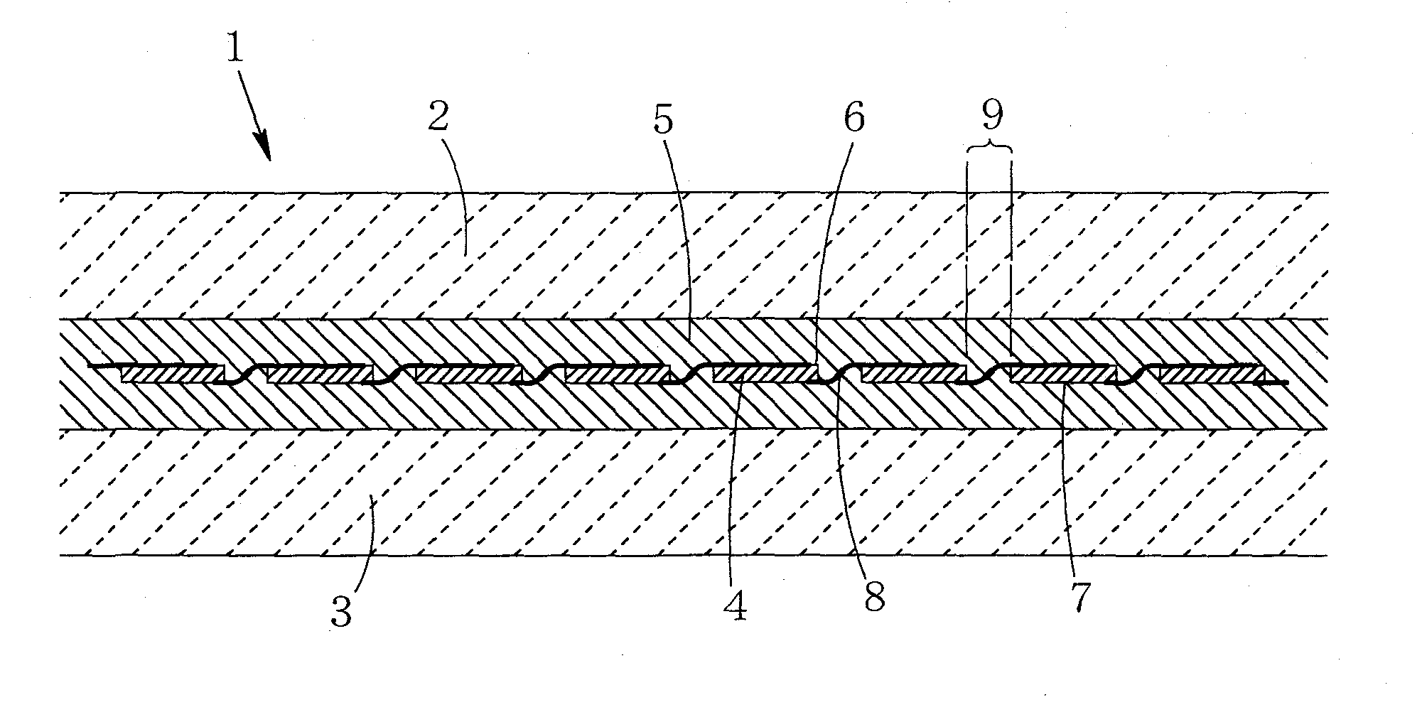
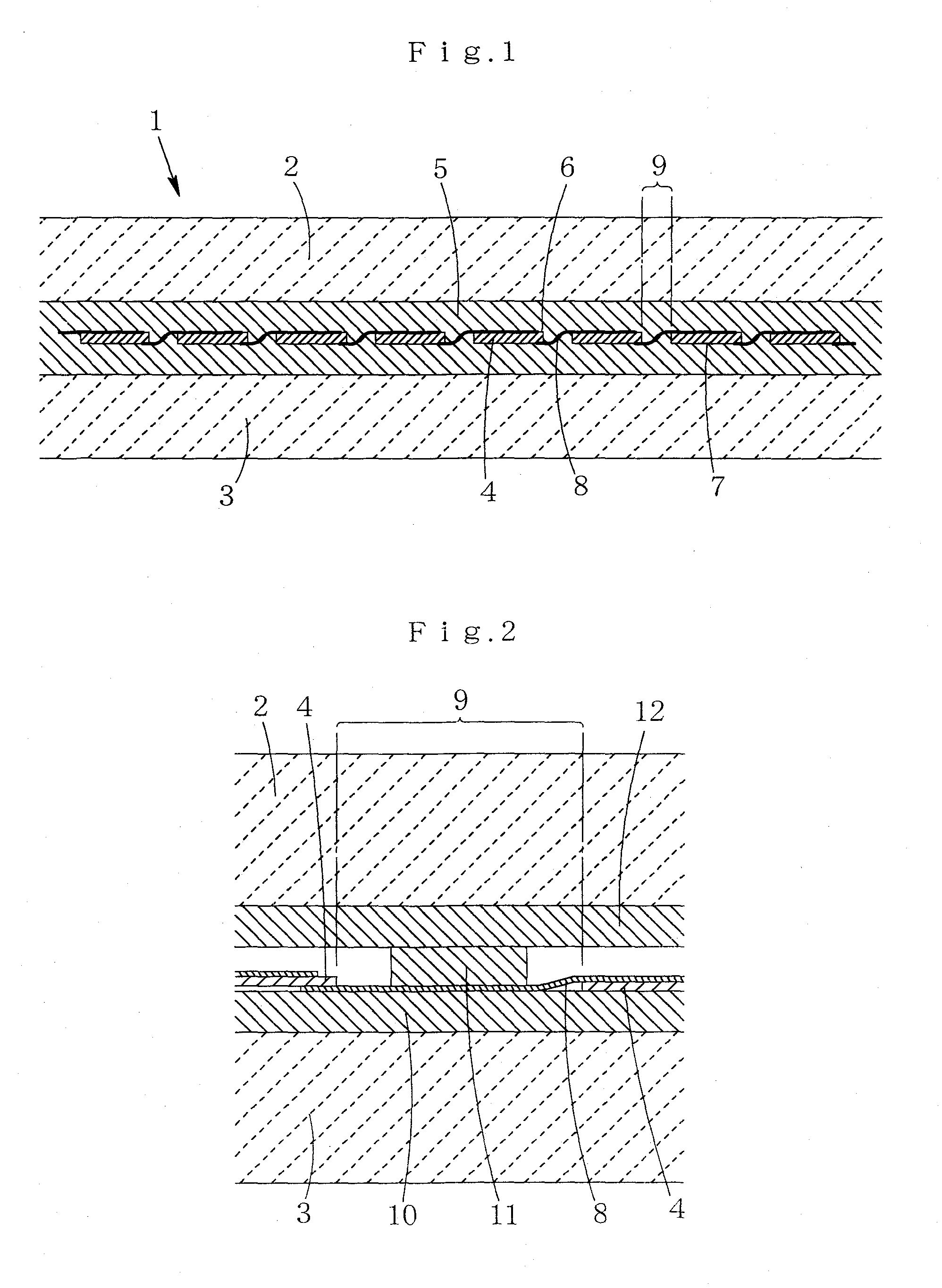
[0080]Forty of square polycrystalline silicon solar battery cells of 125 mm×125 mm×0.35 mm were used as the solar battery cell 4. Four corners are chamfered by approximately several millimeters. A solder dip copper ribbon wire manufactured by Marusho K.K. was used as the conductor 8. The ribbon wire has a width of 1.5 mm and a thickness of 0.25 mm. Solder is previously printed in a portion where the conductor 8 is bouned in light reception surface 6 and the back face 7 of the solar battery cell 4. One end of the conductor 8 was superimposed on a solder printing portion of the light reception surface 6 of the solar battery cell 4 and soldered, and the other end was superimposed on a solder printing portion of the back face 7 of the adjacent solar battery cell 4 and soldered. The cells adjacent to each other were connected to each other by two conductors 8, and a distance thereof was set at 50 mm. That is, the width of the space 9 is 50 mm.

[0081]As the back face panel 3, a float plate...

example 2

[0100]Solar battery modules were obtained in the same manner as in Example 1 by employing the sheet piece arranging pattern A and the sheet piece arranging pattern B, except that the temperature and the pressure at the time of the sealing treatment were changed as shown in Table 2 and FIG. 12.

TABLE 2TreatmenttimeIntegrated timeTemperaturePressure(min)(min)(° C.)(MPa)Step 11127 → 50    0.1 →Step 230317010150 → 7130131711414571 → 74Step 33317874 → 814322181 → 900.075226903025690 → 30125730Step 430287 30 → 15535322155 Step 530352155 → 30 135330 0.07 → 0.1

[0101]In all of the case of employing the sheet piece arranging pattern A and the case of employing the sheet piece arranging material B, the resulting solar battery modules were quite free from occurrence of cell cracks or defects and breakage of the conductor and were not observed with respect to remaining of air bubbles and the flowing out of the sealing resin or sinks in the surroundings. Also, the spaces between the solar battery ...

example 3

[0104]Solar battery modules were obtained in the same manner as in Example 1 by employing the sheet piece arranging pattern A and the sheet piece arranging pattern B, except that the temperature and the pressure at the time of the sealing treatment were changed as shown in Table 3 and FIG. 13.

TABLE 3TreatmenttimeIntegrated timeTemperaturePressure(min)(min)(° C.)(MPa)Step 11120 → 50    0.1 →Step 23031457650 → 7130106711412071 → 74Step 33315374 → 814319681 → 900.073022690Step 430256 90 → 15535291155 Step 530321155 → 30 132230 0.07 → 0.1

[0105]In all of the case of employing the sheet piece arranging pattern A and the case of employing the sheet piece arranging material B, the resulting solar battery modules were quite free from occurrence of cell cracks or defects and breakage of the conductor and were not observed with respect to remaining of air bubbles and the flowing out of the sealing resin or sinks in the surroundings. However, a part of the spaces between the solar battery cells...


PUM


Abstract

Provided is a process of producing a solar battery module 1 including plural solar battery cells 4 sealed by a resin 5 between a transparent panel 2 of the light reception surface side and a back face panel 3, which is characterized by arranging plural solar battery cells 4 at a prescribed interval and mutually connecting them to each other by a conductor 8; arranging a first sealing resin sheet 12 substantially covering the entire surface of the transparent panel 2 of the light reception surface side between the transparent panel 2 of the light reception surface side and the solar battery cells 4; arranging a second sealing resin sheet 10 substantially covering the entire surface of the back face panel 3 between the back face panel 3 and the solar battery cells 4; arranging sealing resin sheet pieces 18, 19 which are thicker than the solar battery cells 4 at a space 9 between the solar battery cells 4 so as to be sandwiched by the first sealing resin sheet 12 and the second sealing resin sheet 10; discharging air between the transparent panel 2 of the light reception surface side and the back face panel 3; and heating the resin 5 for melting and then cooling down it for sealing. According to this, when the plural solar battery cells 4 are arranged and sealed by the resin 5, breakage of the solar battery cells 4 can be prevented from occurring.

Description

TECHNICAL FIELD[0001]The present invention relates to a process of producing a solar battery module. In particular, the invention relates to a process of producing a solar battery module including solar battery cells sealed by a resin between a transparent panel of the light reception surface side and a back face panel.BACKGROUND ART[0002]In recent years, consciousness of the environmental protection has been increasing, and importance of the solar photovoltaic power generation is more increasing. A solar battery cell is sandwiched by protective materials, sealed by a transparent resin, and then provided for use outdoors as a solar battery module. As the transparent resin for sealing, an ethylene-vinyl acetate copolymer (hereinafter sometimes abbreviated as “EVA”) or the like is used, and sealing is conducted by sandwiching the resin between the protective material and the solar battery cell, heat melting and then solidifying it. In order to efficiently arrange the solar battery cel...

Claims


Application Information

Patent Timeline
Patent Type & Authority Applications(United States)
IPC IPC(8): H01L31/0203H01L31/00
CPCB32B17/10036B32B17/10091Y02E10/50H01L31/048H01L31/042
Inventor YUUKI, TAKESHIAKIYAMA, MASARUMASADA, KEIZO
Owner NAKAJIMA GLASS
Why Eureka
Try Eureka