Power-Supply Unit, Hard-Disk Drive, and Switching Method of the Power-Supply Unit

a power supply unit and hard drive technology, applied in the direction of electric variable regulation, process and machine control, instruments, etc., can solve the problems of circuit complexity, circuit complexity, circuit complexity, etc., and achieve the effect of high power conversion efficiency

Inactive Publication Date: 2011-08-11
HITACHI LTD
View PDF13 Cites 83 Cited by
  • Summary
  • Abstract
  • Description
  • Claims
  • Application Information

AI Technical Summary

Benefits of technology

[0012]According to the configuration described above, ON / OFF of the arm switches provided in the full bridge circuit and the two synchronous rectifier switches of the rectifier and smoothing circuit are controlled under a light load so that a resonant peak voltage required for achieving the ZVS, which is determined by the output current flowing in the output terminal, the resonant inductor, and the resonant capacitor, is operated under the condition as if the output current is increased. Then, energy accumulated in the choke coil of the rectifier and smoothing circuit is returned to the full bridge circuit, and a current flowing in the full bridge circuit increases. As a result, the ZVS of the arm switches which are provided in the full bridge circuit can be ensured.
[0013]As described above, according the present invention, there is provided a power-supply unit of an isolation-type DC-DC converter which has high efficiency of power conversion even under a light load.

Problems solved by technology

However, to achieve the ZVS becomes difficult under a light load using this type of power-supply unit, and the efficiency of power conversion decreases.
However, in the method, a circuit component is added to a power block of the power-supply unit, thereby the circuit becomes complex.
Then, the circuit becomes more complex, and a drive loss (energy loss) due to the linear control is generated even under a light load.

Method used


Image

  • Power-Supply Unit, Hard-Disk Drive, and Switching Method of the Power-Supply Unit
  • Power-Supply Unit, Hard-Disk Drive, and Switching Method of the Power-Supply Unit
  • Power-Supply Unit, Hard-Disk Drive, and Switching Method of the Power-Supply Unit

Examples


first embodiment

[0041]Hereinafter, a power-supply unit according to the first embodiment of the present invention will be explained in reference to FIG. 1 to FIG. 12.

[0042]In addition, an embodiment of a switching method of the power-supply unit of the present invention will be explained.

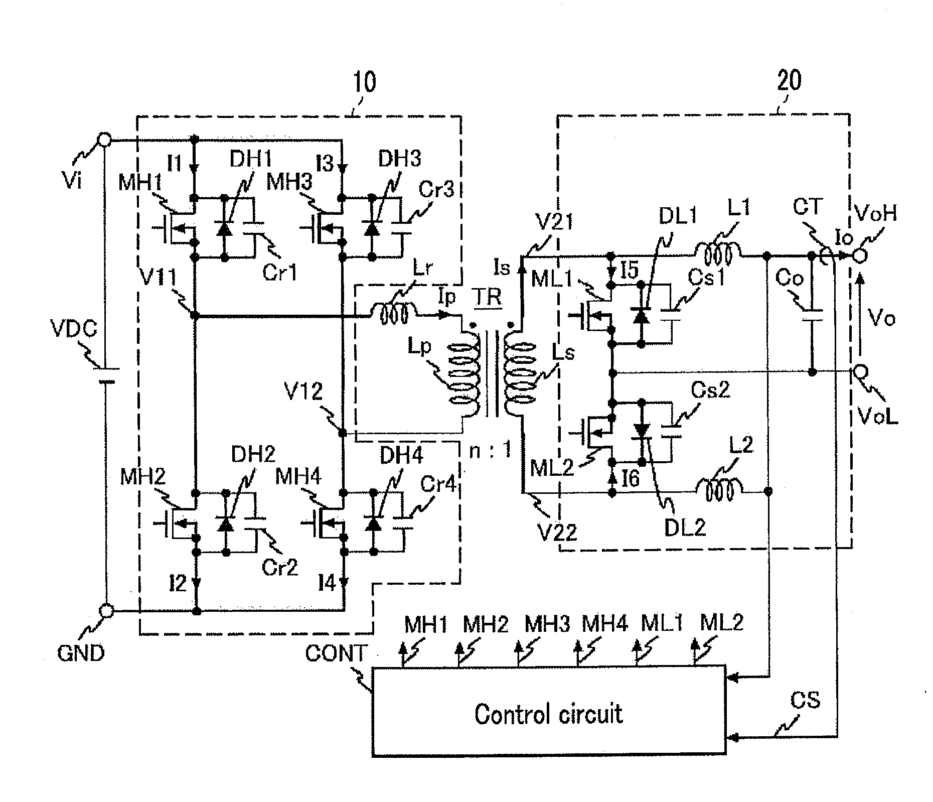
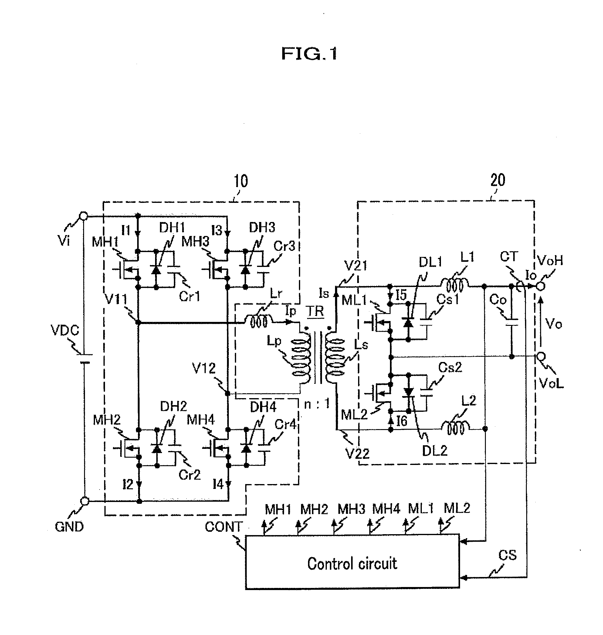
[0043]FIG. 1 is a circuit diagram showing the first embodiment is of a power-supply unit of an isolation type DC-DC converter to which the present invention is applied.

[0044]In FIG. 1, a reference TR is a transformer, and a reference 10 shown with a dotted line is a full bridge circuit which AC-drives a primary coil Lp of the transformer TR. A reference 20 shown with a dotted line is a current doubler type (full-wave type) rectifier and smoothing circuit which converts AC voltage induced in the primary coil Ls of the transformer TR to DC voltage through synchronous conversion. A reference CONT is a control circuit which controls operation timings of arm switches MH1 to MH4 constituting the full bridge circuit 10 an...

second embodiment

[0126]A second embodiment of the power-supply unit of the present invention is shown in FIG. 14.

[0127]In FIG. 14, a reference TR is a transformer, and a reference 10 shown with a dotted line is a full bridge circuit which AC-drives a primary coil Lp of the transformer TR. A reference 20 shown with a dotted line is a current doubler type rectifier and smoothing circuit which converts AC voltage induced in a secondary coil Ls of the transformer TR to DC voltage through synchronous conversion. A reference CONT is a control circuit which controls operation timings of arm switches MH1 to MH4 constituting the full bridge circuit 10 and consisting of MOSFETs and operation timings of synchronous rectifier switches ML1, ML2 consisting of MOSFETs in the current doubler type rectifier and smoothing circuit 20.

[0128]Here, basic configurations of the full bridge circuit 10 and the control circuit CONT are the same with those in FIG. 1. On the other hand, configurations of the transformer TR and ...

third embodiment

[0133]A hard-disk drive according to an embodiment of the present invention is shown in FIG. 15.

[0134]FIG. 15 is an example of a HDD apparatus (Hard Disk Drive, hereinafter, referred to as HDD apparatus) to which the present invention is applied. The HDD apparatus is provided with a power source system of a parallel redundancy structure. When AC voltage is received, the power source system outputs an output voltage Vo through PFC (Power Factor Correction) circuits PFC1, PFC2 and the isolation type DC-DC converters (Iso DC-DC1, Iso DC-DC2) that are described in the first embodiment or the second embodiment. The output voltage Vo is given power outage measures by connecting a buckup power supply BUPS which mounts a battery.

[0135]In addition, the output voltage Vo supplies power to the HDD apparatuses (HDD1 to HDDm) through non-isolation type DC-DC converters (DC-DC11 to DC-DC1m). In addition, the output voltage Vo supplies power to a processor CPU (Central Processing Unit) managing a ...


PUM

PropertyMeasurementUnit
peak voltageaaaaaaaaaa
DC voltage VDCaaaaaaaaaa
currentaaaaaaaaaa

Abstract

A power-supply unit which comprises a transformer, a full bridge circuit consisting of four arm switches provided on a primary side of the transformer, a rectifier and smoothing circuit including two synchronous rectifier switches provided on a secondary side of the transformer, a choke coil, and a capacitor, an output terminal provided in the rectifier and smoothing circuit, a control circuit controlling ON/OFF of the four arm switches of the full bridge circuit and the two synchronous rectifier switches of the rectifier and smoothing circuit, a resonant inductor consisting of a leakage inductor component of the transformer and a parasitic inductor component of wirings on the primary side of the transformer, and a resonant capacitor consisting of a parasitic capacitor component of the arm switches of the full bridge circuit, and in which the control circuit comprises timing variable means which varies switching timings of the two synchronous rectifier switches of the rectifier and smoothing circuit based on an output current flowing in the output terminal provided in the rectifier and smoothing circuit.

Description

CROSS REFERENCE TO RELATED APPLICATIONS[0001]This application claims the foreign priority benefit under Title 35, United States Code, §119(a)-(d) of Japanese Patent Application No. 2010-027352, filed on Feb. 10, 2010, the contents of which are hereby incorporated by reference.BACKGROUND OF THE INVENTION[0002]1. Field of the Invention[0003]The present invention relates to a power-supply unit of a DC-DC converter and, in particular, concerns to efficiency improvement of an isolation type DC-DC converter under a light load thereof.[0004]2. Description of Related Art[0005]A power-supply unit of a DC-DC converter is required to have high efficiency of power conversion in a wide load range from energy saving / energy conservation point of view. Therefore, a power-supply unit having a full bridge circuit at the primary side and a current doubler type rectifier and smoothing circuit at the secondary side is used to attain the high efficiency of power conversion with a soft-switching technolog...

Claims


Application Information

Patent Timeline
Patent Type & Authority Applications(United States)
IPC IPC(8): G11B21/02H02M3/335
CPCH02M3/33592H02M2001/0032H02M2001/0048Y02B70/16Y02B70/1475Y02B70/1491Y02B70/1433Y02B70/10H02M1/0032H02M1/0048H02M1/0058
Inventor SASE, TAKASHIKANOUDA, AKIHIKOTSUYUKI, YOSUKE
Owner HITACHI LTD
Why Eureka
Try Eureka