Fixing member, manufacturing method thereof, and fixing apparatus

Active Publication Date: 2011-08-11
CANON KK
View PDF15 Cites 13 Cited by
  • Summary
  • Abstract
  • Description
  • Claims
  • Application Information

AI Technical Summary

Benefits of technology

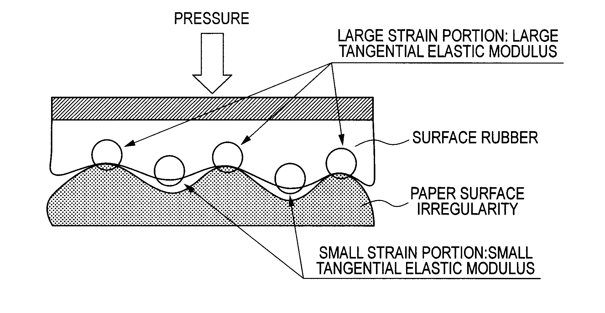
[0006]However, as a result of the study by the present inventors, the following finding has been obtained. More specifically, the higher the conformability to the depressed portion of a sheet of paper by softening the surface layer of the fixing member, the more insufficient the power to press toner particles present on the raised portion of the paper, and the particle shape of the toner particles is maintained. Thus, the gloss of a toner image on the raised portion of the paper surface may b

Problems solved by technology

More specifically, the higher the conformability to the depressed portion of a sheet of paper by softening the surface layer of the fixing member, the more insufficient the power to press toner particle

Method used


Image

  • Fixing member, manufacturing method thereof, and fixing apparatus
  • Fixing member, manufacturing method thereof, and fixing apparatus
  • Fixing member, manufacturing method thereof, and fixing apparatus

Examples


example 1

[0056]An addition-reactive liquid silicone rubber was coated on the outer peripheral surface of a stainless-steel hollow cylindrical core metal with an outer diameter of 80 mm by a ring coating method and heated at a temperature of 200° C. for 4 hours, to form an elastic material layer made of silicone rubber having a thickness of 500 μm. A primer (trade name: MEGUM3290, manufactured by Chemetall Inc.) was applied on the peripheral surface of the elastic material layer so as to have a thickness of 2 μm and dried. On the other hand, the materials in Table 2 as below were dissolved in 900 g of methyl isobutyl ketone, to prepare a solution for forming a surface layer.

TABLE 2Fluoropolymer including a terpolymer of100gvinylidene fluoride, tetrafluoroethylene andperfluoro methyl vinyl ether each havingiodine in a molecule as a reaction group(trade name: Daiel LT302, manufactured byDaikin Industries, Ltd.)A copolymerizable silicone surfactant in which50gdimethylpolysiloxane and a polyoxyal...

example 2

[0062]The materials described in Table 3 as below were dissolved in 900 g of methyl isobutyl ketone, to prepare a solution for forming a surface layer.

TABLE 3Fluoropolymer including a terpolymer of100gvinylidene fluoride, tetrafluoroethylene andperfluoro methyl vinyl ether each havingiodine in a molecule as a reaction group(trade name: Daiel LT302, manufactured byDaikin Industries, Ltd.)A copolymerizable silicone surfactant in which50gdimethylpolysiloxane and a polyoxyalkylene arealternately and repeatedly combined with eachother (trade name: FZ-2207, manufactured byDow Corning Toray Silicone Co., Ltd.)TAIC (manufactured by Nippon Kasei Chemical8gCo., Ltd.)Benzoyl peroxide (water content: 25%,8gmanufactured by Kishida Chemical Co., Ltd.)

[0063]A fixing member was manufactured in the same manner as in Example 1 except using the solution for forming a surface layer described above, and evaluated in the same manner as in Example 1.

example 3

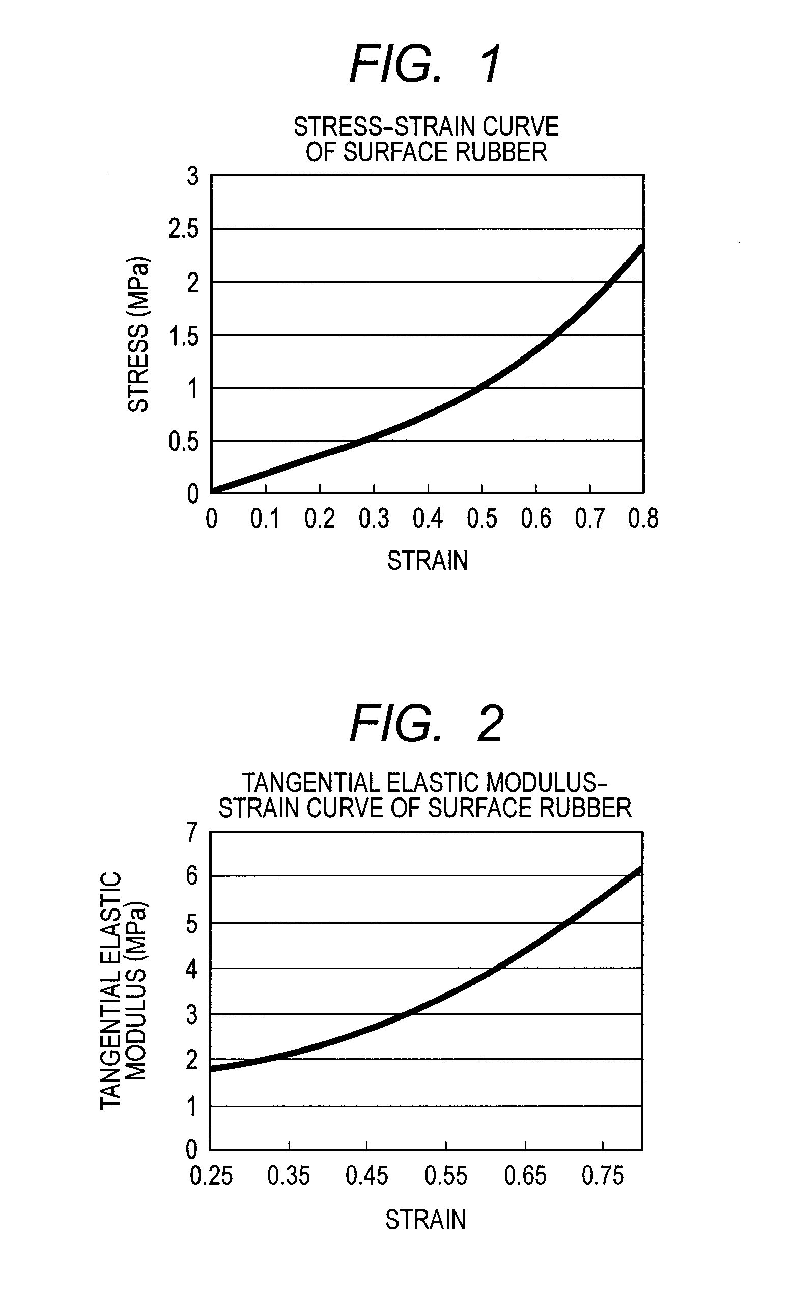
[0064]A fixing member was produced in the same manner as in Example 1 except changing the oxygen concentration at electron beam irradiation in Example 1 to 20 ppm. It was confirmed that the stress-strain curve of a surface layer of the fixing member was not different from that of Example 1. In addition, the resulting fixing member was evaluated in the same manner as in Example 1.


PUM


Abstract

The present invention relates to a fixing member that can apply sufficient power to press toner particles on a raised portion of a paper surface while also maintaining good conformability to a depressed portion of the paper surface that is an advantage of a surface layer including a soft rubber layer. The fixing member has a surface layer to come into contact with toner, the surface layer has a sea-island structure in which the fluororubber constitutes a sea phase and a silicone compound having a crosslinked structure constitutes an island phase, and in a stress-strain curve of the surface layer, the tangential elastic modulus, the slope of the curve, increases as the strain increases, in the strain range of 0.25 to 0.8.

Description

[0001]This application is a continuation of International Application No. PCT / JP2010 / 007549, filed Dec. 27, 2010, which claims the benefit of Japanese Patent Application No. 2010-000582, filed Jan. 5, 2010.BACKGROUND OF THE INVENTION[0002]1. Field of the Invention[0003]The present invention relates to a fixing member used for thermal fixing of an electrophotographic image and a manufacturing method thereof, and a fixing apparatus.[0004]2. Description of the Related Art[0005]A toner image obtained in an electrophotographic image forming apparatus is formed on various recording materials. Among them, a sheet of paper most commonly used as a recording material has irregularities due to paper fibers on its surface, and a toner image is formed on the irregularities. Unfixed toner particles formed on the sheet of paper is crushed by heating while being pressed by a fixing member, so as to fix on the paper surface. In a case where a surface layer of the fixing member is hard, a toner prese...

Claims


Application Information

Patent Timeline
IPC IPC(8): G03G15/20
CPCG03G15/2057G03G2215/2051
Inventor KITANO, YUJIABE, KATSUYA
Owner CANON KK
Why Eureka
Try Eureka