
Method and Apparatus for Amplifying Nucleic Acid Sequences

Inactive Publication Date: 2011-08-11
LUDWIG MAXIMILIANS UNIV MUNCHEN
View PDF6 Cites 1 Cited by
  • Summary
  • Abstract
  • Description
  • Claims
  • Application Information

AI Technical Summary

Benefits of technology

[0012]There is still a need in the art for an improved method of, and an apparatus for, replicating amplification nucleic acid sequences. In particular, there is a need in the art for a method of and an apparatus for replicating nucleic acid sequences which do not suffer from the problems associated with the large thermal mass of conventional PCR cyclers and the complexity of some microfluidic chip designs. There is further a need in the art for a method of, and an apparatus for, replicating nucleic acid sequences that allows for nucleic acid sequences to be accumulated in one region or plural regions of a reaction vessel in a controllable manner. There is further a need in the art for a method of, and an apparatus for, selectively replicating / amplifying a selected target sequence. A method and the apparatus shall be suitable for rapidly and efficiently amplifying a wide variety of nucleic acid sequences.

Problems solved by technology

However, PCR cyclers that apply a temperature sequence to a reaction vessel may be costly.
Further, many conventional PCR cyclers have a large thermal mass, which makes it challenging to realize rapid temperature changes.
A major problem with nucleic acid amplification via PCR is the generation of unspecific amplification products.
Very often this is due to an unspecific oligonucleotide priming and subsequent primer extension event prior to the actual thermosizing procedure itself.
While such microfluidic chips do not suffer from a large thermal mass which imposes limits on temperature change rates, manufacture of microfluidic chips may be costly.
Further, depending on the design of the microfluidic chip, micropumps and / or microvalves may need to be provided to drive the solution through the microfluidic chip, which adds to the costs of the PCR setup.
It may be challenging to accommodate different vessel widths in an apparatus for replicating nucleic acid sequences by PCR.

Method used


Image

  • Method and Apparatus for Amplifying Nucleic Acid Sequences
  • Method and Apparatus for Amplifying Nucleic Acid Sequences
  • Method and Apparatus for Amplifying Nucleic Acid Sequences

Examples


Embodiment Construction

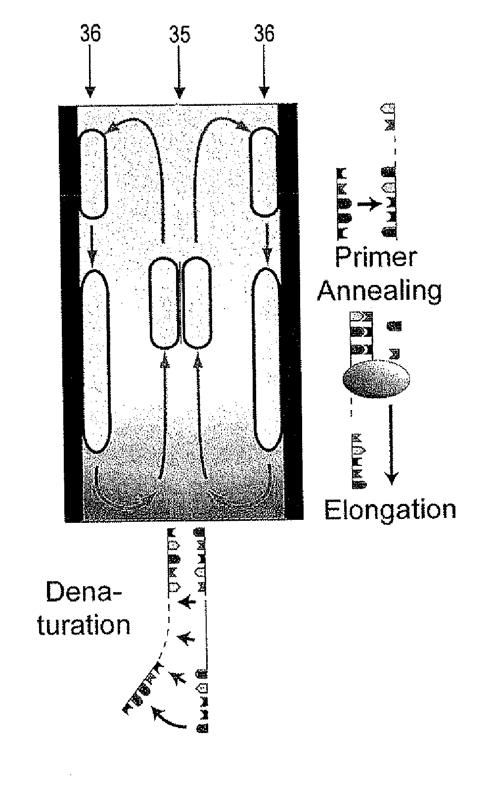
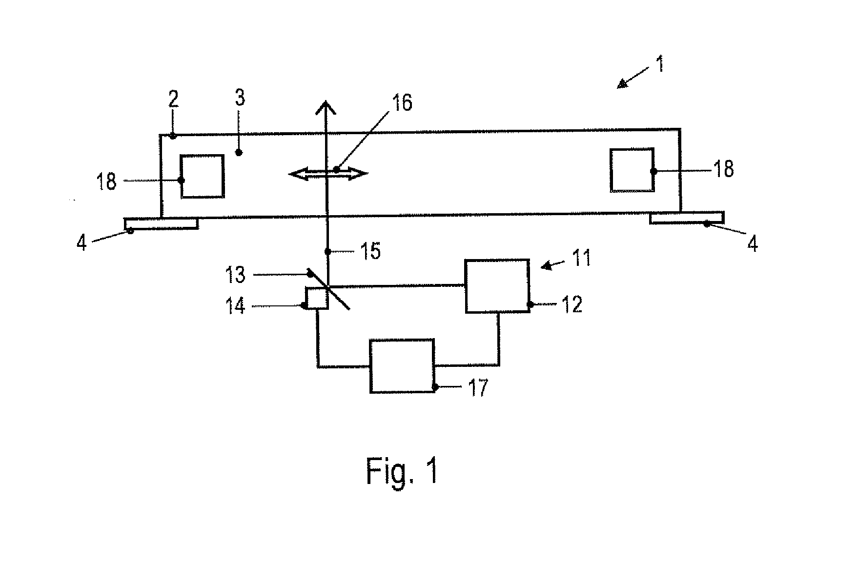
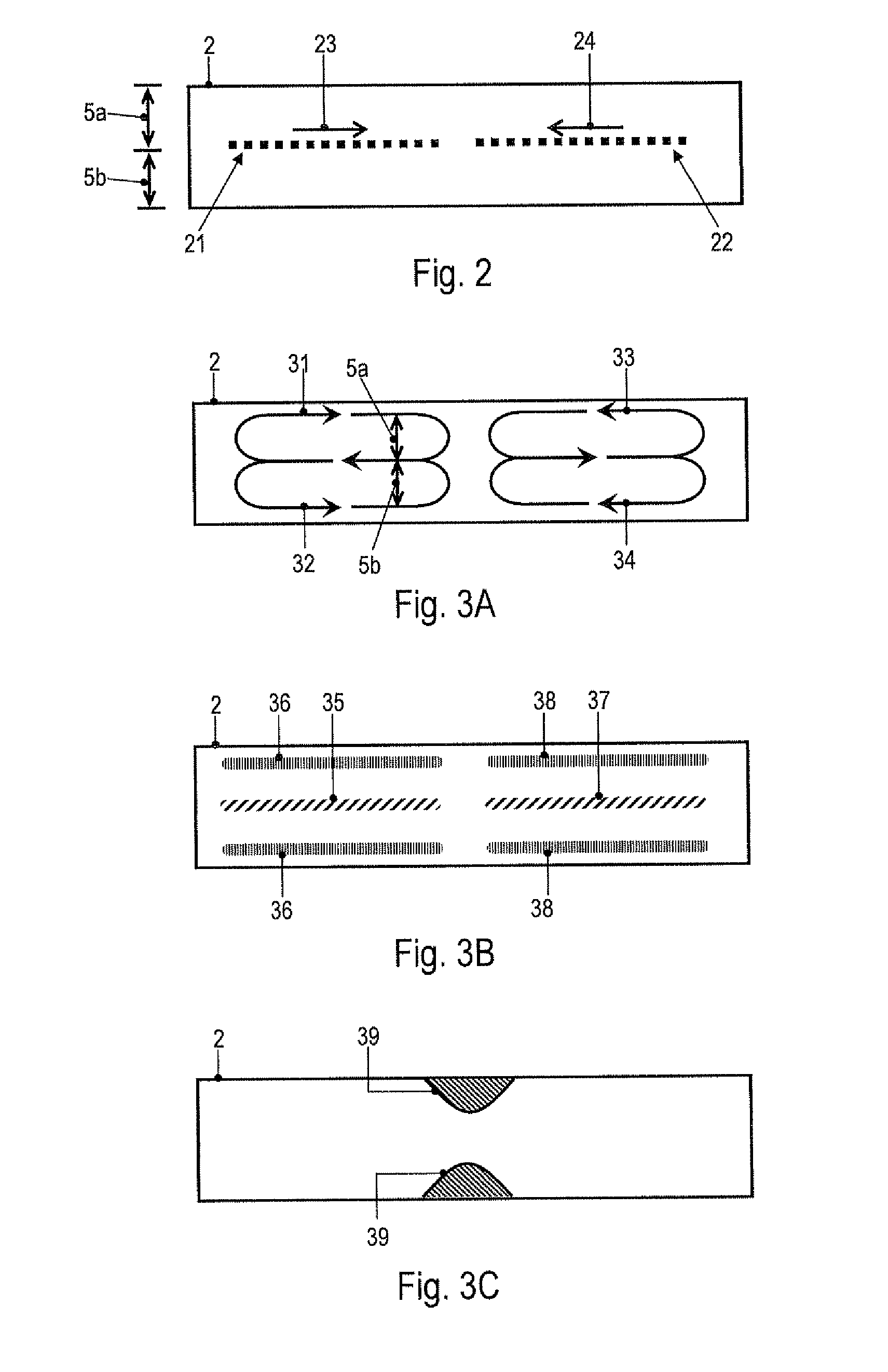
[0052]In embodiments of the invention, a fluid flow is established in the PCR buffer solution by supplying heating power to the PCR buffer solution at a plurality of positions in a time-varying manner, i.e., by using a spatio-temporally varying heating. This mechanism drives fluid flow and allows the velocity of the fluid flow within the vessel to be adjusted. It has been surprisingly found that adjusting the velocity of the fluid flow within the vessel may be used to generate and control a local concentration increase of molecules or particles in the PCR buffer solution. The mechanism is selective in the sense that, for a given velocity of the fluid flow, the obtained concentration changes are more pronounced for one type of molecules, complexes or particles than for other types of molecules, complexes or particles. It is noted that the term “selective” does not preclude that more than one type of molecules, complexes or particles is accumulated in a region of the vessel. Moreover,...


PUM

PropertyMeasurementUnit
Temperatureaaaaaaaaaa
Flow rateaaaaaaaaaa
Ratioaaaaaaaaaa

Abstract

A method of amplifying one or more target nucleic acid sequence(s) in a PCR buffer solution comprising one or more target nucleic acid sequence(s), a nucleic acid polymerase, deoxynucleotide or nucleotide triphosphates, at least a first primer and a second primer is provided. The PCR buffer solution is contained in an elongated vessel. The solution within the vessel is locally heated in a spatio-temporally varying manner. Fluid flows circulating within the vessel are established. At least a fraction of the PCR buffer solution cyclically travels between regions having different temperatures, giving rise to a temperature cycling.

Description

PRIORITY[0001]The present U.S. patent application claims priority from European Patent Application EP 10001234.3, entitled, “Method and Apparatus for Amplifying Nucleic Acid Sequences” filed Feb. 5, 2010, which is incorporated herein by reference in its entirety.FIELD OF INVENTION[0002]The invention relates to a method of and an apparatus for amplifying a nucleic acid sequence. The invention relates in particular to a method and an apparatus that allow a nucleic acid sequence to be amplified by polymerase chain reaction (PCR).BACKGROUND ART[0003]The polymerase chain reaction (PCR) has become the conventional technique used to amplify specific DNA or RNA sequences. U.S. Pat. No. 4,683,202 and U.S. Pat. No. 4,683,195 describe the basic PCR technique. Since the first disclosure of the PCR method, it has had a profound effect on the practice of biotechnology and biomedical science. A wide range of applications, such as the replication of DNA specimens in DNA forensics or in medical diag...

Claims


Application Information

Patent Timeline
IPC IPC(8): C12P19/34C12M1/00
CPCB01L3/5027B01L3/502715C12Q1/686B01L2400/0454B01L3/50273B01L7/525B01L2200/0631B01L2300/0816B01L2300/0838B01L2300/1822B01L2300/1872B01L2400/0445B01L2400/0451C12Q2527/15C12Q2527/101
Inventor BRAUN, DIETERMAST, CHRISTOF
Owner LUDWIG MAXIMILIANS UNIV MUNCHEN
Learn More