receiver

a receiver and receiver technology, applied in the field of receivers, can solve the problems of inability difficult to eliminate interference waves, and possible degradation of reception signals

Active Publication Date: 2011-08-18
FUJITSU LTD
View PDF4 Cites 22 Cited by
  • Summary
  • Abstract
  • Description
  • Claims
  • Application Information

AI Technical Summary

Benefits of technology

[0010]According to an embodiment, a receiver receives a reception signal subjected to orthogonal frequency division multiplexing modulation or orthogonal frequency division multiple access modulation. The receiver has: an array antenna having a plurality of antennas for receiving the reception signal; adaptive equalizers, each of which is provided in each of the plurality of antennas, and each of which reduces advanced waves or delayed waves having a delay time set with respect to a main wave in the reception signal; a spatial diversity combining portion which multiplies each of output signals of the adaptive equalizers by a weighting coefficient and adds the multiplied signals; a weight control portion which generates the weighting coefficient based on each of the output signals of the adaptive equalizers; and an equalizer setting unit which estimates an arrival angle for each path and a delay time for each path of the reception signal, and based on each of the estimated arrival angles and delay times of a plurality of paths, decides an interference wave for elimination to be eliminated by the adaptive equalizers among interference waves whose delay time with respect to the main wave exceeds a guard interval time, and sets in the adaptive equalizers the delay time of the interference wave for elimination with respect to the main wave.

Problems solved by technology

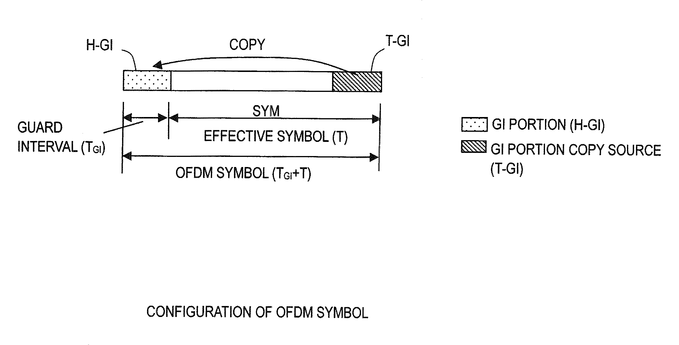
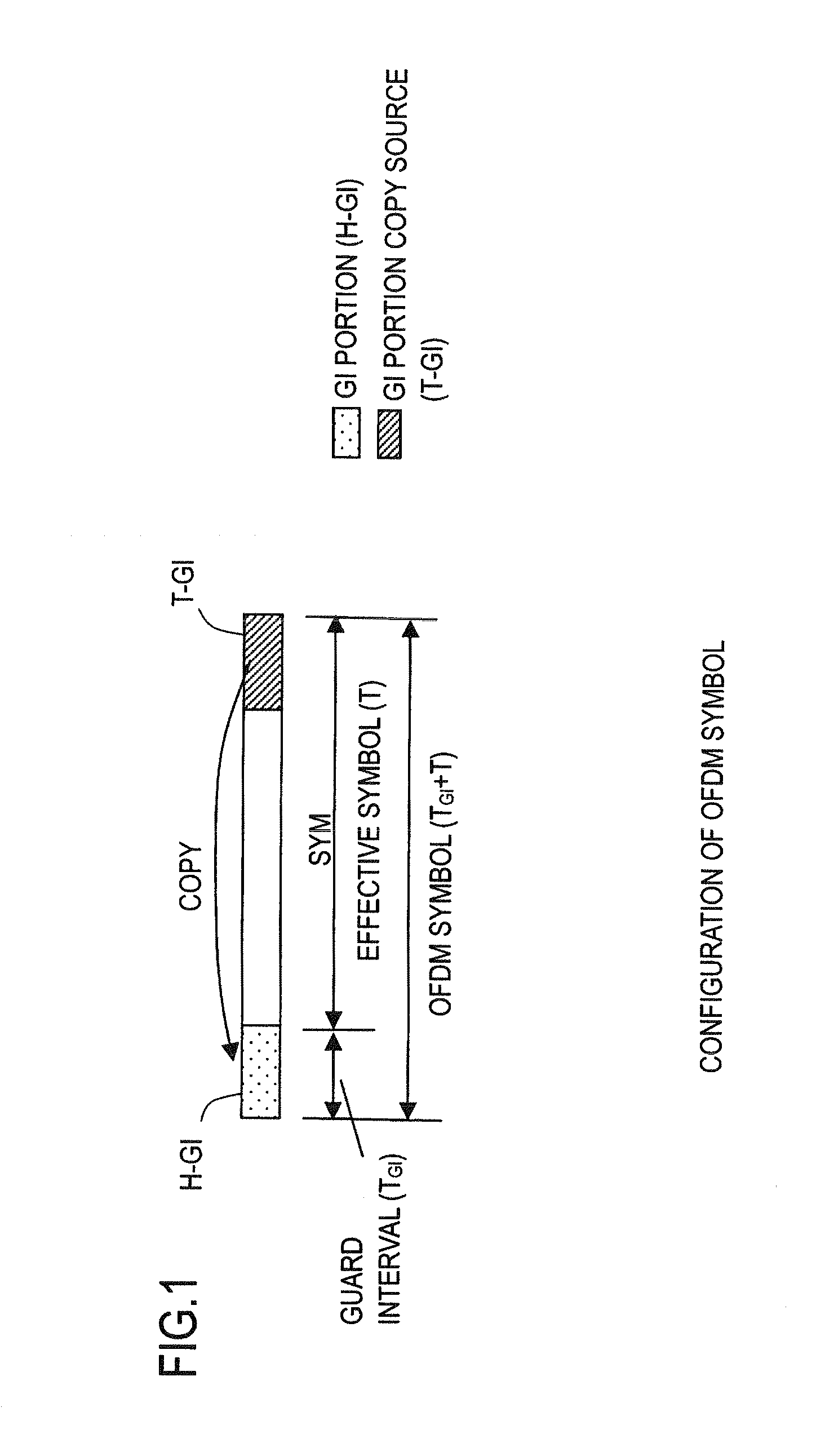
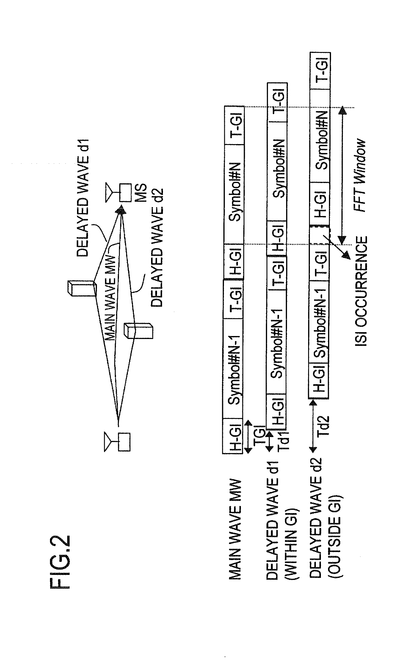
However, if a delayed wave and advanced wave occur with a delay amount exceeding the GI interval, adjacent symbols enter within the FFT window, and there is interference from adjacent symbols.
That is, intersymbol interference (ISI) occurs, and degradation of the reception signal may occur.
The effect of spatial diversity in suppressing interference waves has the characteristic of depending on the arrival angle for each path; when the arrival angles of an interference wave and the desired wave are close, there is the problem that interference wave elimination is difficult.
Also, there is the problem that, when eliminating an interference wave by spatial diversity combining, if the number of paths exceeds the degrees of freedom of the array antenna (the sum of the number of directional beams and the number of directional nulls), interference wave elimination is not possible.

Method used


Image

  • receiver
  • receiver
  • receiver

Examples


embodiments

[0053]FIG. 4 depicts in summary the configuration of the receiver of this embodiment. This receiver has four antennas AT1 to AT4, and, for each antenna, a high-frequency circuit RF which down-converts the frequency of the received wave, and an adaptive equalizer 10-1 to 10-4 which attenuates those interference waves, among advanced waves and delayed waves with respect to the main wave due to multipath propagation, for which the delay time exceeds the guard interval time. Also, the receiver has a spatial diversity combining portion 16 which multiplies the output signals of the adaptive equalizers 10-1 to 10-4 by weighting coefficients w1 to w4 and adds the results, and a weight control portion 14 which generates the weighting coefficients w1 to w4 based on the output signals of the adaptive equalizing means. The output of the spatial diversity combining portion 16 is subjected to FFT processing to convert from time-domain signals y(t) to frequency-domain signals Y(f). FFT may also be...

first embodiment

[0076]FIG. 7 depicts a configuration of the receiver of a first embodiment, which is a more specific configuration of the device of FIG. 4. In FIG. 7, due to space constraints, only two antennas AT1 and AT2 are depicted, but the antenna may be an adaptive array antenna having four antennas, as in FIG. 4, or a plurality of antennas equal to or greater than four. In each of the antennas AT1, AT2 are provided high-frequency reception circuits RF, analog / digital conversion circuits ADC, and adaptive equalizers 10-1, 10-2. And, delay amounts τpre and τpost are set as TAP delay position information in the adaptive equalizers 10-1, 10-2 by the TAP delay amount setting portion 12A. This TAP delay amount setting portion 12A is provided with delay information for interference waves to be equalized, decided in advance by the equalizer setting unit 12 using the above-described algorithm. By this means, interference waves are equalized and attenuated from the output signals x1′ (t), x2′(t) of th...

second embodiment

[0105]FIG. 15 depicts the configuration of the receiver of a second embodiment. This receiver is provided with a high-frequency circuit RF and an analog / digital converter ADC for each of two antennas AT1, AT2. And, the adaptive equalizer 10-2 of FIG. 8 is provided on the side of the antenna AT2. On the other hand, a fixed delay circuit 40 and a subtractor 43 are provided on the side of the antenna AT1. And, a replica generation portion 41 which generates a replica signal x1″(t) from the output signal x2′(t) of the adaptive equalizer 10-2 on the side of the antenna AT2 is provided; the replica signal x1″(t) generated thereby is subtracted from the reception signal x1(t) on the side of the antenna AT1 by the subtractor 43, to equalize the interference wave. To this end, a coefficient computation portion 42 is provided which computes coefficient values from the output signal x2′(t) of the adaptive equalizer 10-2 and the output signal x1′(t) of the subtractor 43 and provides it to the r...


PUM


Abstract

A receiver receives a reception signal subjected to orthogonal frequency division multiplexing modulation or orthogonal frequency division multiple access modulation. The receiver has: an array antenna for receiving the reception signal; adaptive equalizers provided in each of the plurality of antennas, and reducing advanced or delayed waves having a delay time to a main wave in the reception signal; a spatial diversity combining portion which multiplies output signals of the adaptive equalizers by a weighting coefficient and adds the multiplied signals; a weight control portion generating the weighting coefficient; and an equalizer setting unit which estimates an arrival angle and a delay time for each path of the reception signal, and based on the estimation, decides an interference wave to be eliminated by the adaptive equalizers among interference waves, and sets in the adaptive equalizers the delay time of the decided interference wave.

Description

CROSS-REFERENCE TO RELATED APPLICATIONS[0001]This application is based upon and claims the benefit of priority of the prior Japanese Patent Application No. 2010-033152, filed on Feb. 18, 2010, and the Japanese Patent Application No. 2010-285278, filed on Dec. 22, 2010, the entire contents of which are incorporated herein by reference.BACKGROUND OF THE INVENTION[0002]1. Field of the Invention[0003]The present invention relates to a receiver in an OFDM or OFDMA communication system.[0004]2. Description of the Related Art[0005]OFDM (Orthogonal Frequency Division Multiplexing) and OFDMA (Orthogonal Frequency Division Multiple Access) communication systems are widely used in digital terrestrial broadcasting, WiMAX, and other systems. In an OFDM or OFDMA communication system, a transmitter uses transmission data to modulate a plurality of subcarriers the frequencies of which are orthogonally related, the OFDM frequency-domain signals are subjected to IFFT and converted into OFDM time-doma...

Claims


Application Information

Patent Timeline
Patent Type & Authority Applications(United States)
IPC IPC(8): H04L27/06H04L27/01H04L1/02
CPCH04B7/0854H04B7/0857H04L27/2647H04L27/2601H04L25/03019
Inventor UMEDA, MASATAKAIWAMATSU, TAKANORI
Owner FUJITSU LTD
Why Eureka
Try Eureka