
Optical System Determination According to Advanced Criteria

a technology of optical system and advanced criteria, applied in optics, instruments, material analysis, etc., can solve the problems of unclear vision, limited number of criteria taken into account, and inability to answer all lens wearer needs, so as to achieve better optical system calculation

Active Publication Date: 2011-08-18
ESSILOR INT CIE GEN DOPTIQUE
View PDF7 Cites 20 Cited by
  • Summary
  • Abstract
  • Description
  • Claims
  • Application Information

AI Technical Summary

Benefits of technology

[0007]The present invention makes it possible to consider a large number of criteria in order to achieve a better optical system calculation, closer to the user needs.
[0020]v. Modifying at least one parameter of the working optical system, in order to minimize a cost function considering target values and criterion values by repeating step iv till a stop criterion is satisfied.
[0039]Central vision (also referred as foveal vision) describes the work of the fovea, a small area in the center of the retina that contains a rich collection of cones. In a central vision situation, an observer looks at an object which stays in a gaze direction and the fovea of the observer is moved to follow the object. Central vision permits a person to read, drive, and perform other activities that require fine and sharp vision.
[0076]It is generally difficult to optimize a lens considering a lot of criteria which are from different natures if only the equation of one surface is considered as variable. This embodiment enables optical designers to take into account a larger number of criteria in the optimization process and is paving the way for optical system geometrical performance enhancement and better answer to physiological needs of lens wearers. The benefit for the wearer is improved when several surfaces of the optical system are simultaneously optimized.

Problems solved by technology

Optimization methods for optical system calculation are well known; however, currently the number of criteria taken into account is limited and do not enable to answer all lens wearer needs.
Known methods present drawbacks arising from the fact that classical criteria aim at improving only optical quality of the image caused by optical aberrations like power and astigmatism errors.
These aberrations induce blurring in the image and a drop in contrast, causing therefore unclear vision.
Classical criteria do not enable to improve other kind of performance such as image deformations and localisation which are main issues for enhancing wearer adaptation and answering user specific needs in general.

Method used


Image

  • Optical System Determination According to Advanced Criteria
  • Optical System Determination According to Advanced Criteria
  • Optical System Determination According to Advanced Criteria

Examples


Embodiment Construction

[0105]Skilled artisans appreciate that elements in the figures are illustrated for simplicity and clarity and have not necessarily been drawn to scale. For example, the dimensions of some of the elements in the figures may be exaggerated relative to other elements to help improve the understanding of the embodiments of the present invention.

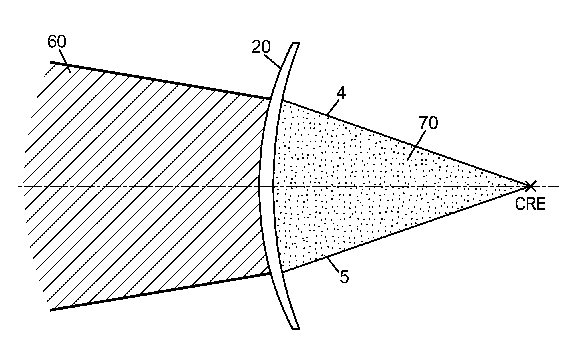
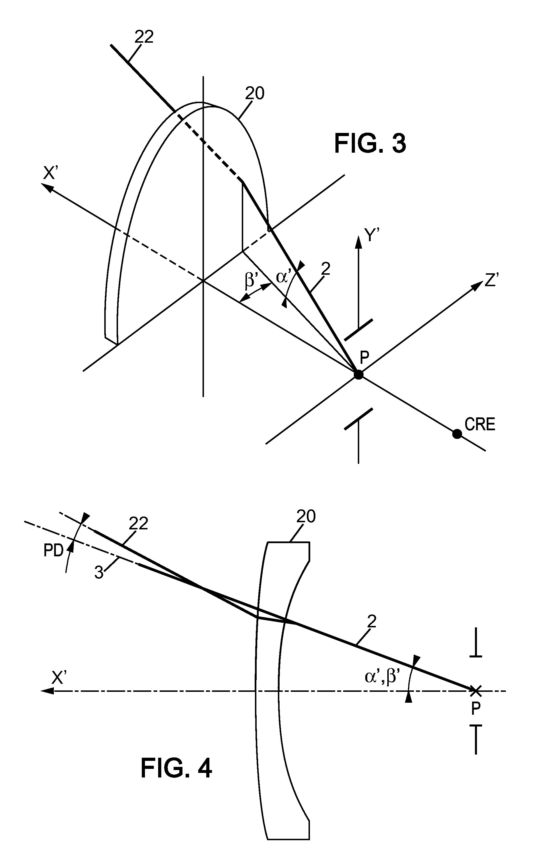
[0106]We focus first on the criterion evaluation method according to the vision situation (central or peripheral). In order to compute a criterion, ray tracing software can be used. Ray tracing has special features according to the model of the lens-plus-eye system.

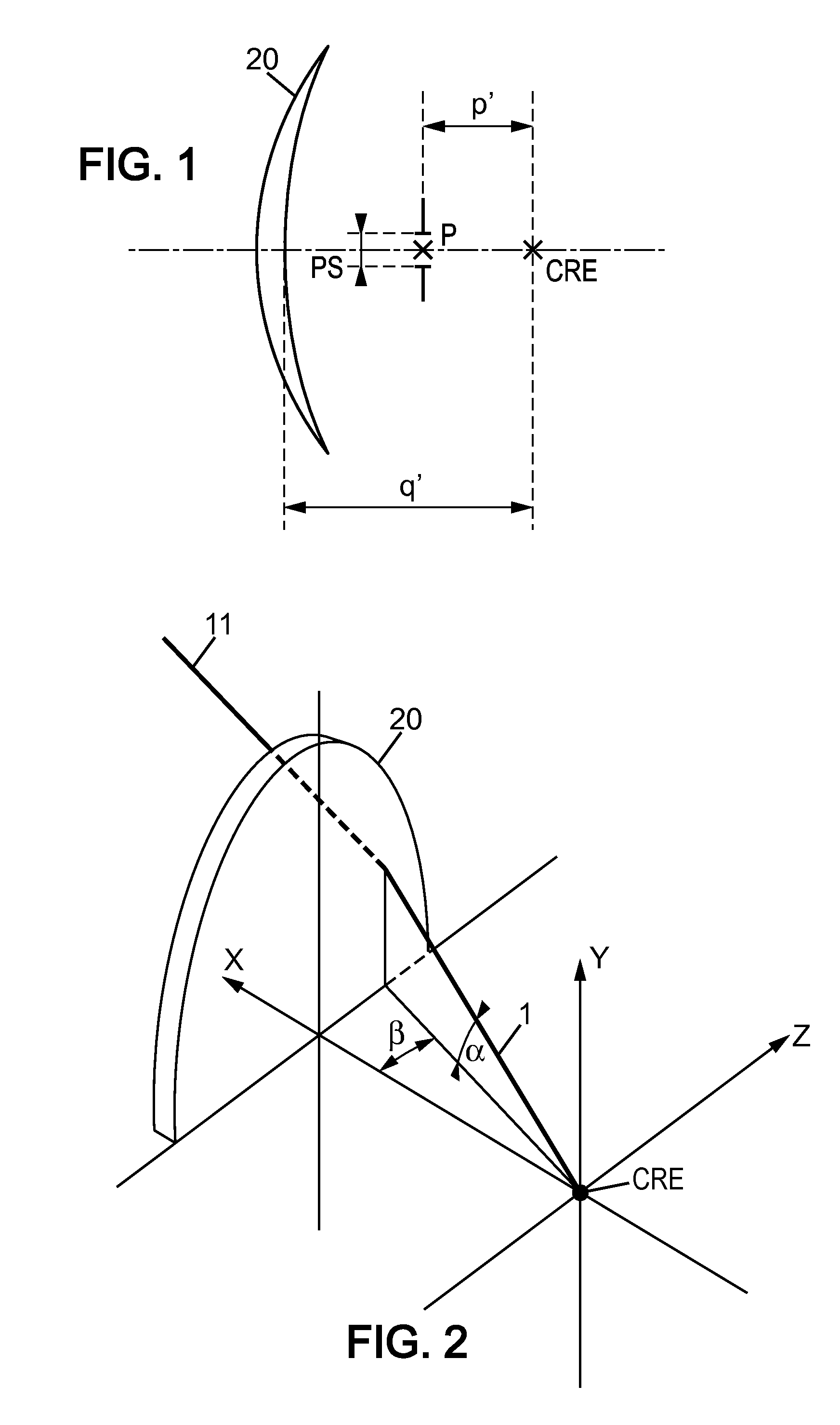
[0107]FIG. 1 illustrates a schematic view of a lens-plus-eye system. Referring to FIG. 1, an eye position can be defined by the center of rotation of the eye CRE and the entrance pupil central point P. PS is the pupil size (not drawn to scale). The distance q′ between the CRE and the lens 20 is generally, but not limited to, set to 25.5 mm, and p′ defines the position of the eye entran...


PUM


Abstract

A method implemented by computer means for calculating by optimization an optical system for example an ophthalmic lens according to at least one criterion among the following list consisting of: ocular deviation, object visual angular field in central vision, image visual angular field in central vision, pupil field ray deviation, object visual angular field in peripheral vision, image visual angular field in peripheral vision, prismatic deviation in peripheral vision, magnification in peripheral vision, lens volume, magnification of the eyes, temple shift, or a variation of preceding criteria.

Description

RELATED APPLICATIONS[0001]This is a U.S. National Phase Application under 35 USC 371 of International Application PCT / EP2009 / 063569 filed on Oct. 16, 2009.[0002]This Application claims the priority of European Application No. 08305693.7 filed Oct. 16, 2008, the entire content of which is hereby incorporated by reference.FIELD OF THE INVENTION[0003]The invention relates to a method for calculating by optimization an optical system, for example and not limitedly the optical system represents an ophthalmic lens. More specifically, the invention relates to a method for determining parameters of an optical system implementing an optimization of criteria.BACKGROUND OF THE INVENTION[0004]Optimization methods for optical system calculation are well known; however, currently the number of criteria taken into account is limited and do not enable to answer all lens wearer needs. French patent FR 9812109 of the Applicant describes for example a method for determining optimal parameters for an o...

Claims


Application Information

Patent Timeline
Patent Type & Authority Applications(United States)
IPC IPC(8): G06F19/00
CPCG02C7/02G02C7/061G02C7/028G02C7/024
Inventor DE ROSSI, HELENEMURADORE, FABIEN
Owner ESSILOR INT CIE GEN DOPTIQUE
Learn More