Wet scrubber and a method of cleaning a process gas

Active Publication Date: 2011-08-25
GENERAL ELECTRIC TECH GMBH
View PDF7 Cites 25 Cited by
  • Summary
  • Abstract
  • Description
  • Claims
  • Application Information

AI Technical Summary

Benefits of technology

[0018]According to one embodiment, the absorption liquid flow supplied to each active nozzle is less than 180 m3/hour, corresponding to 180000 litres/hour, or 3000 litres/minute. The Total Flow of the spray level system is preferably less than 200 m3/hour/m2. An advantage of this embodiment is that it provides for efficient sulphur dioxide absorption without requiring unnecessarily high flows of absorption liquid.
[0019]According to one embodiment, the process gas flows substantially vertically upwards through the wet scrubber vertical tower towards said spray level system at a process gas vertical velocity of less than 8 m/s. A higher process gas vertical velocity than 8 m/s tends to strongly increase the flue gas pressure drop as measured over the wet scrubber and the energy consumption without further improving the sulphur dioxide absorption efficiency.
[0020]A further object of the present invention is to provide a wet scrubber that is more efficient in removing sulphur dioxide from a process gas than the prior art wet scrubber.
[0021]This object is achieved by means of a wet scrubber operative for cleaning a process gas containing sulphur dioxide. The wet scrubber comprises at least one spray level system operative for receiving a flow of absorption liquid therethrough and for atomizing said absorption liquid by means of atomizing nozzles. The spray level system comprises an active nozzle density of at least 0.7 nozzles per m2 of internal wet scrubber horizontal cross-sectional area. When the spray level system is operated in HC operating mode, each of the active atomizing nozzles disperse an absorption liquid flo

Problems solved by technology

A disadvantage of the wet scrubber of U.S. Pat. No. 5,620,144 is that the wet scrubber tower is a high piece of equipment, which makes it a costly investment and maintenance item.
Furthermore, in combustion plants combusting various types and/or loads of fuels, it is difficult to control the sulfur diox

Method used


Image

  • Wet scrubber and a method of cleaning a process gas
  • Wet scrubber and a method of cleaning a process gas
  • Wet scrubber and a method of cleaning a process gas

Examples


Embodiment Construction

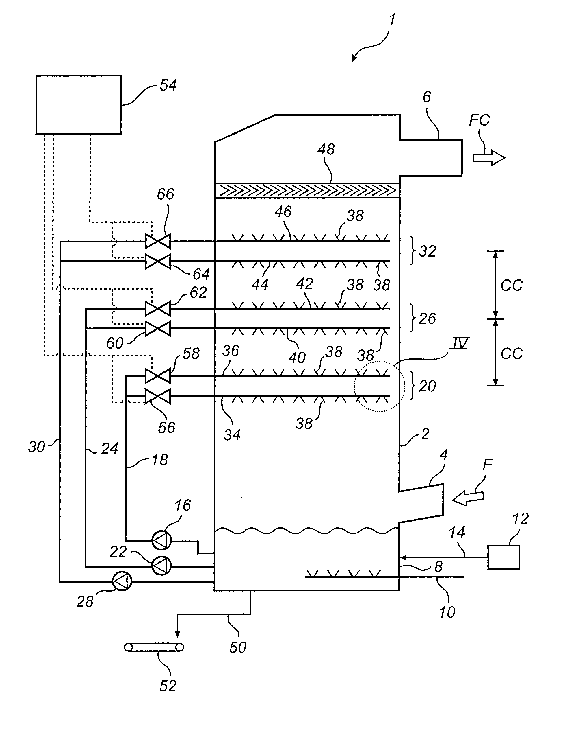
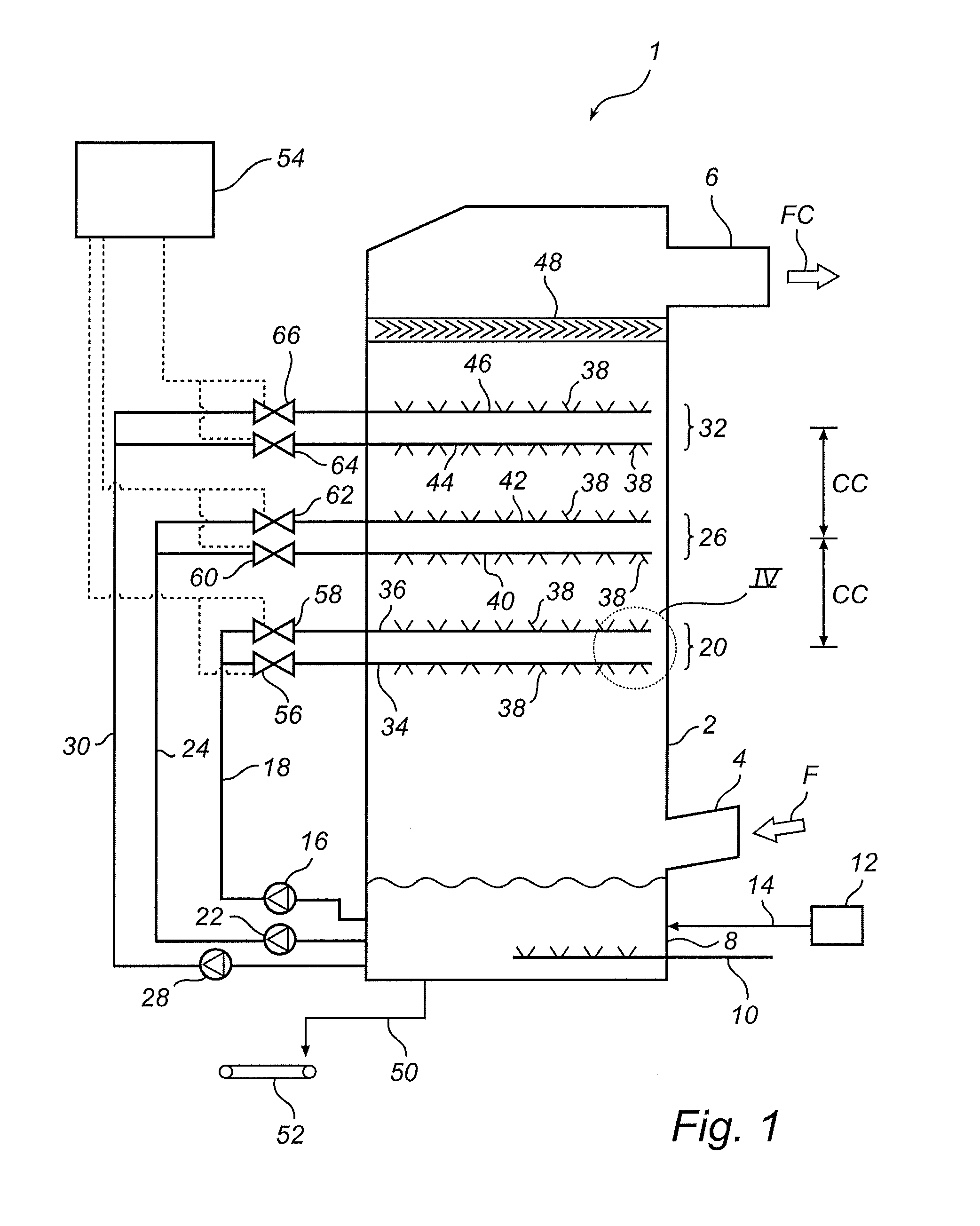
[0035]FIG. 1 illustrates a wet scrubber 1. The wet scrubber 1 is operative for removing at least a portion of the sulphur dioxide content of a process gas, in the form of a flue gas, F, generated in a boiler (not shown) which is operative for combusting a fuel, such as coal or oil.

[0036]The wet scrubber 1 comprises a vertical open tower 2, an inlet 4 for flue gas, F, to be cleaned, and an outlet 6 for flue gas, FC, from which at least a portion of the sulphur dioxide content has been removed.

[0037]An absorption liquid tank 8 is arranged at the bottom of the vertical open tower 2. The absorption liquid tank 8 is provided with an oxidation arrangement 10. Fresh limestone, CaCO3, is supplied to the absorption liquid tank 8 from an absorbent supply device comprising a limestone storage 12 and a supply pipe 14. It will be appreciated that absorption liquid tank 8 may, as an alternative, be positioned outside of tower 2, and that the supply of limestone could, as an alternative, enter the...


PUM

PropertyMeasurementUnit
Flow rateaaaaaaaaaa
Volumetric flow rateaaaaaaaaaa
Speedaaaaaaaaaa

Abstract

A wet scrubber (1) and a method of using the wet scrubber to clean a process gas containing sulphur dioxide comprising at least one spray level system (20) with atomizing nozzles (38) to which an absorption liquid is supplied for atomization by the nozzles (38). The method comprises operating the spray level system (20) in at least a first operating mode with an active nozzle density of at least 0.7 nozzles/m2, an absorption liquid flow of at least 10 m3/hour per nozzle and a Total Flow of at least 30 m3/hour/m2.

Description

FIELD OF THE INVENTION[0001]The present invention relates to a method of cleaning a process gas containing sulphur dioxide by means of a wet scrubber comprising at least one spray level system with atomizing nozzles to which an absorption liquid is supplied and atomized by the atomizing nozzles.[0002]The present invention further relates to a wet scrubber being operative for cleaning a process gas containing sulphur dioxide, the wet scrubber comprising at least one spray level system with atomizing nozzles which is operative for receiving an absorption liquid and for atomizing said absorption liquid by means of the atomizing nozzles.BACKGROUND OF THE INVENTION[0003]In the combustion of a fuel, such as coal, oil, peat, waste, etc., in a combustion plant, such as a power plant, a hot process gas is generated, such process gas containing, among other components, sulfur oxides, such as sulfur dioxide, SO2. Sulfur dioxide is an environmental pollutant. Hence, it is necessary to remove at...

Claims


Application Information

Patent Timeline
IPC IPC(8): B01D47/06B01D53/14
CPCF01N3/0871B01D53/185B01D2259/124B01D53/79B01D53/504
Inventor HAKANSSON, RIKARD
Owner GENERAL ELECTRIC TECH GMBH
Why Eureka
Try Eureka