Electric Connection System

a technology of electric connection system and electric connection, which is applied in the direction of electric devices, machines/engines, agricultural machines, etc., can solve the problems of poor efficiency of the tractor-trailer combination composed of the utility vehicle and the attachment, poor actuation efficiency of the tractor-trailer combination, and the inability to use the attachments with electrical loads which have a relatively high power consumption for carrying out agricultural work functions, etc., to achieve the highest possible level of efficiency of the utility vehicl

Active Publication Date: 2011-08-25
DEERE & CO
View PDF9 Cites 27 Cited by
  • Summary
  • Abstract
  • Description
  • Claims
  • Application Information

AI Technical Summary

Benefits of technology

[0043]To permit the highest possible level of efficiency of the utility vehicle and/or of the attachment to be achieved, it is possible to provide a control loop which has the power electronics system of the utility vehicle and/or a control device. The control loop can communicate with sensors and/or controllers of the utility vehicle and/or of the attachment and have a communications network for transmitting data. By means of this control loop it is possible, for example, to control the abovementioned pulse width and/or pulse f

Problems solved by technology

Both the mechanical and the hydraulic transmission of power between the utility vehicle and the attachment entail problems in terms of actuation.
This may result in a poor level of efficiency of the tractor-trailer combination composed of the utility vehic

Method used


Image

  • Electric Connection System
  • Electric Connection System
  • Electric Connection System

Examples


Embodiment Construction

[0052]Identical or similar components are identified with the same reference symbols in the figures.

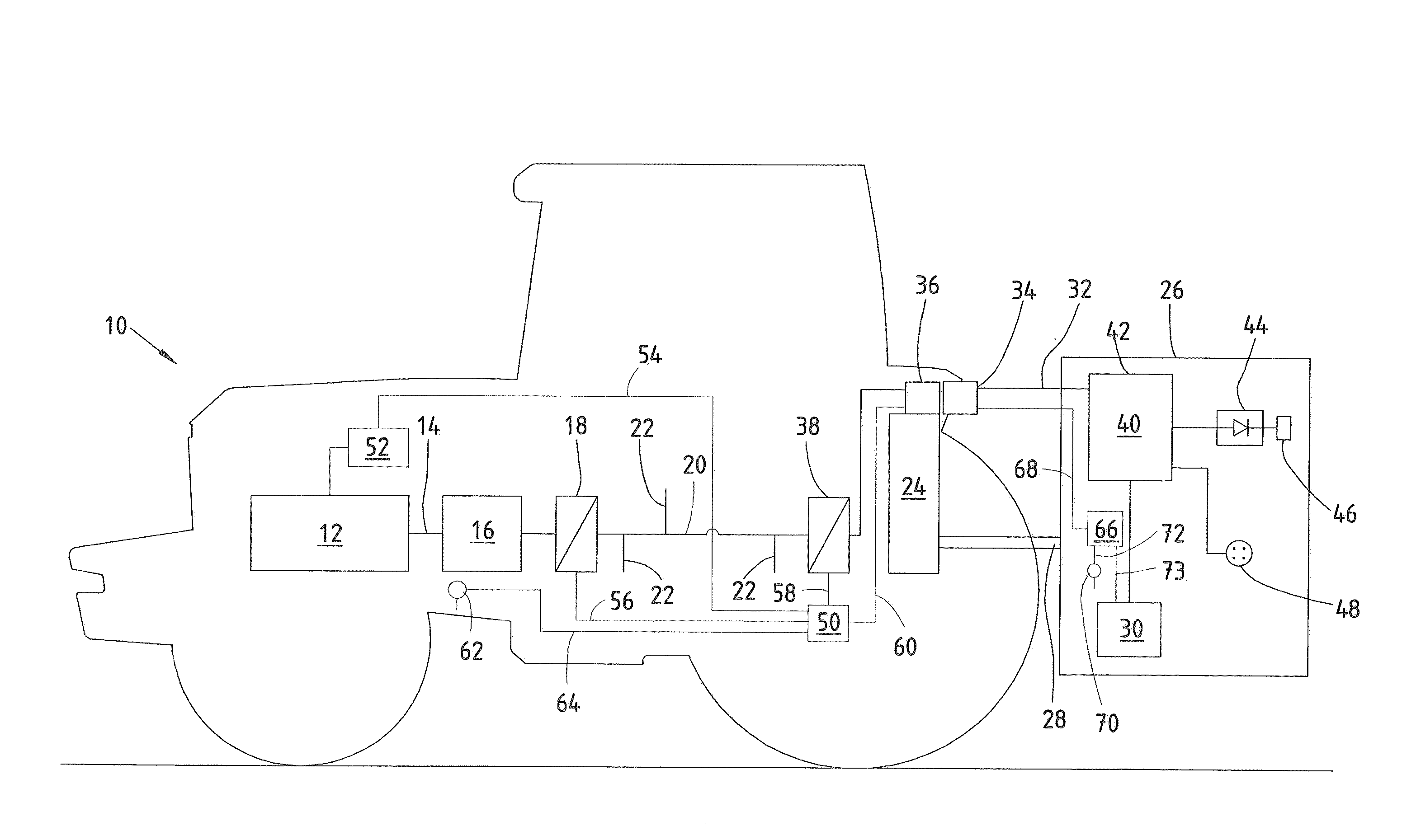
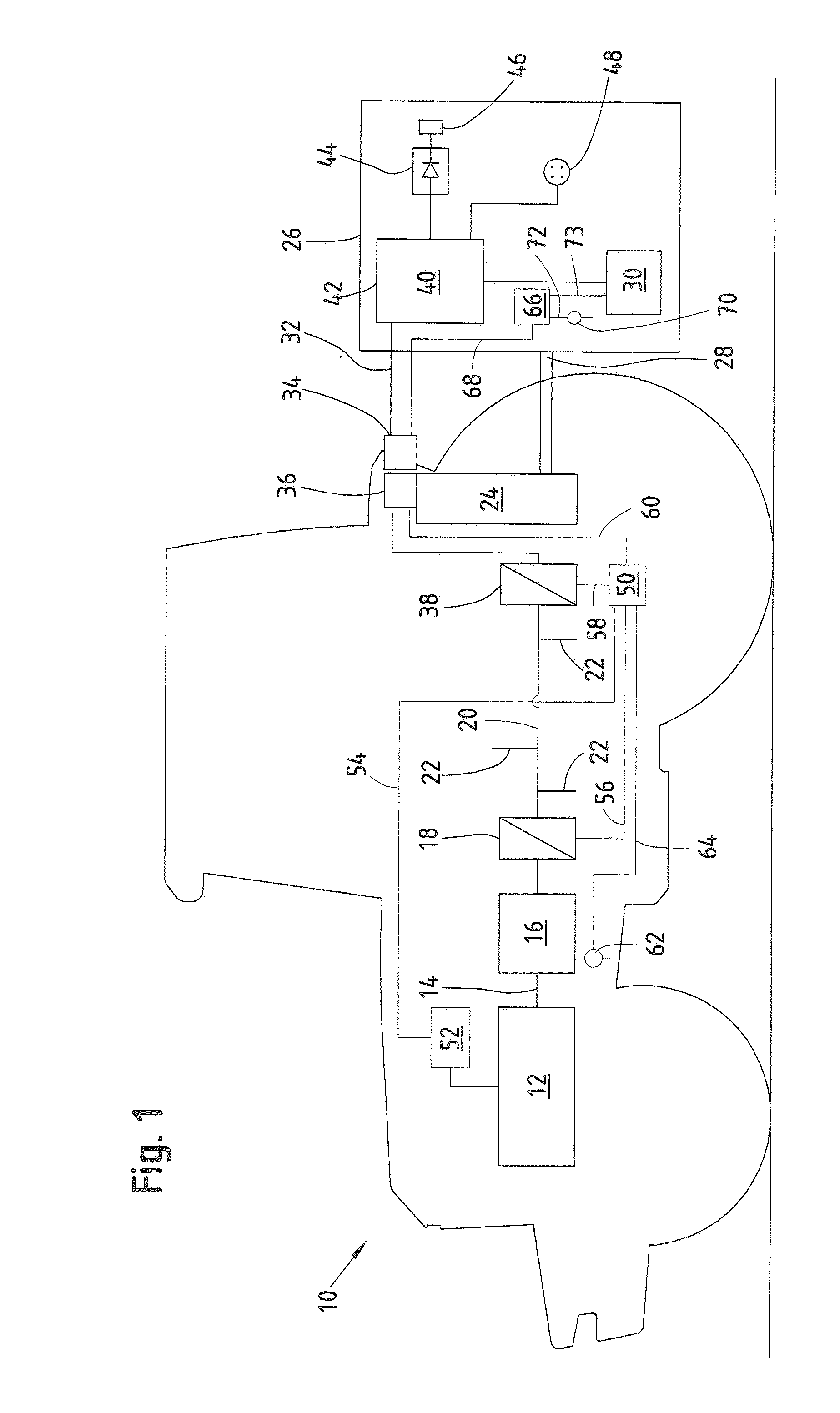
[0053]FIG. 1 shows an agricultural utility vehicle 10 which is embodied in the form of a tractor. In the text which follows, the tractor is also denoted by the reference symbol 10. The tractor 10 has an internal combustion engine 12. On the one hand, the locomotive drive for the tractor 10 is driven via a gear mechanism (not shown in FIG. 1) by the output shaft 14 of the internal combustion engine 12. On the other hand, the output shaft 14 drives the generator 16. The generator 16 is permanently installed on the tractor 10. Specifically, the generator 16 is embodied in the form of a crankshaft generator and is attached by its stator to the motor housing and by its rotor to the flywheel of the internal combustion engine 12. The generator 16 generates 3-phase alternating current which is converted into direct current by means of the power converter 18 of the generator 16 and a rectifier...


PUM


Abstract

The invention relates to a device for transmitting electrical energy from an agricultural utility vehicle (10) to an attachment (26) which can be reversibly coupled to the utility vehicle (10). The device comprises at least one power electronics system (38, 74) which is arranged on the utility vehicle side, at least one electrical utility vehicle interface (36) and at least one electrical attachment interface (34). The power electronics system (38, 74) can be supplied with electrical energy which can be generated by a generator (16) of the utility vehicle (10). The power electronics system (38, 74) can be connected electrically to the generator (16) and to the utility vehicle interface (36). The attachment (26) has at least one attachment interface (34) and at least one electrical load (30, 102, 104). An agricultural working function can be carried out with the electrical load (30, 102, 104) of the attachment (26). At least one utility vehicle interface (36) can be coupled to at least one attachment interface (34), and in this way at least some of the electrical energy which is generated by the generator (16) of the utility vehicle (10) can be transmitted to the attachment (26) via the utility vehicle interface (36).

Description

BACKGROUND OF THE INVENTION[0001]The present invention relates to a device for transmitting electrical energy from an agricultural utility vehicle to an attachment which can be detachably attached to the utility vehicle.[0002]Agricultural utility vehicles such as, for example field choppers, self-propelling spraying devices and tractors are known from the prior art. A tractor is a versatile utility vehicle since different attachments can be coupled to a tractor. Ploughs, harrows, grubbers, seeders, spraying machines, rotary mowers and round balers are usually coupled. Accordingly a tractor with a respectively coupled attachment carries out a wide variety of agricultural working functions. This makes it also necessary for the tractor to actuate the respective attachment in a corresponding way if the agricultural working function which is carried out with the attachment is carried out with an actuator, a tool or with a motor. But also different harvesting attachments for a combine har...

Claims


Application Information

Patent Timeline
IPC IPC(8): B60L1/00
CPCA01B59/06B60K6/485B60K6/40F02D29/06A01B59/00
Inventor TARASINSKI, NICOLAIHAHN, KLAS
Owner DEERE & CO
Why Eureka
Try Eureka