
Image processing method and method of three-dimensional printing incorporating the same

Active Publication Date: 2011-08-25
SYNOPSYS INC
View PDF46 Cites 81 Cited by
  • Summary
  • Abstract
  • Description
  • Claims
  • Application Information

AI Technical Summary

Benefits of technology

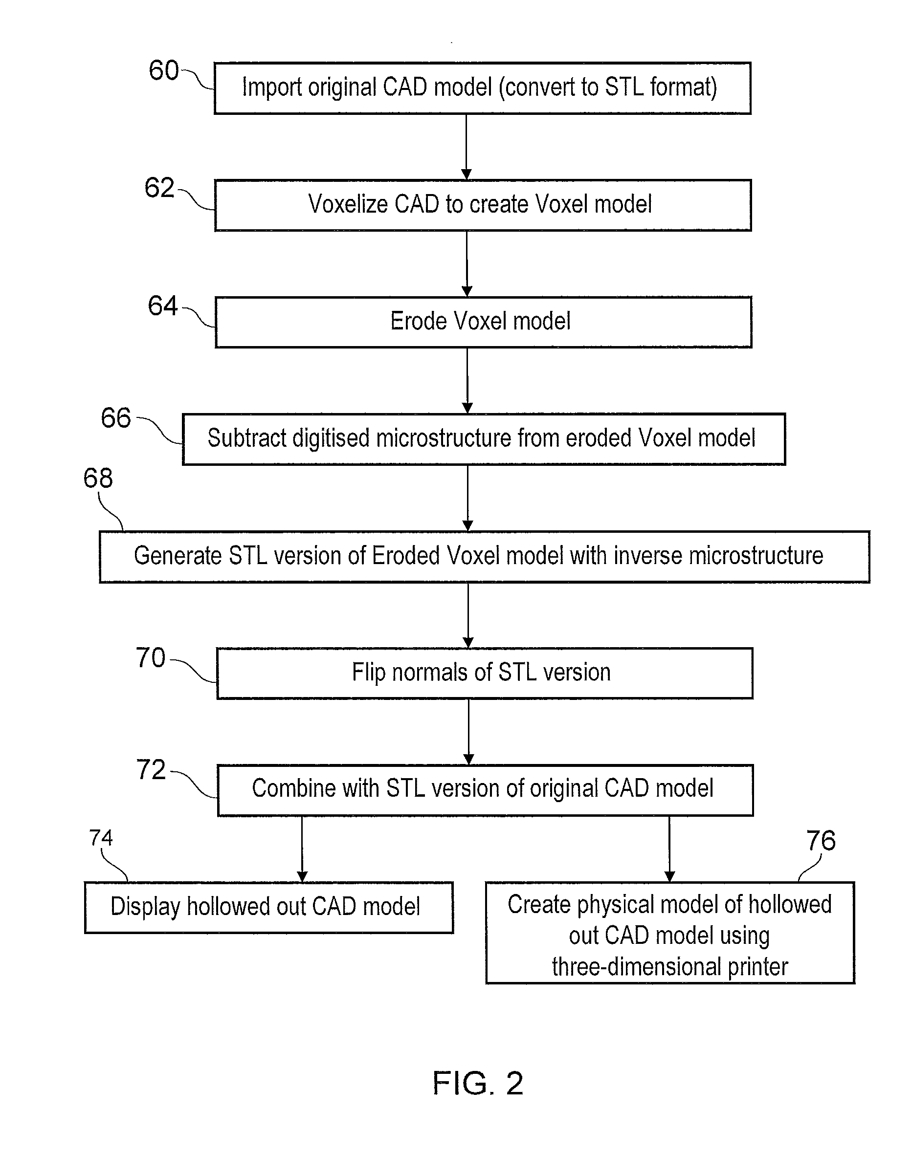
[0009]Obtaining a voxelized three-dimensional representation of a three-dimensional CAD model is a lossy transformation, and as such is a counter-intuitive step for those wishing to obtain an accurate physical model by three-dimensional printing, for whom remaining in CAD form is seen as essential. However, the present invention is built on the unexpected realisation that a switch to a digitised representation to create an interior surface (which can subsequently be converted to a vector-based surface representation) both improves the robustness of the shelling process and provides an efficient mechanism for introducing an internal microstructure. Moreover, because the new surfaces generated from the eroded model and the original CAD surfaces are nested, and therefore do not come into contact, appropriate computer descriptions of the internal surfaces generated can simply be concatenated with the original CAD model to form a new hollowed CAD model.
[0015]A particular advantage of eroding a digitised representation to obtain an internal volume is the ease at which problems arising from the intersection of inwardly moved surfaces are avoided, because by definition the erosion acts to shrink the object rather than merely displacing its surfaces.
[0023]Combining the vector-based surface representations of the virtual three-dimensional object and the internal volume may comprise performing a concatenation operation to unify sets of data corresponding to the original CAD representations of the virtual three-dimensional object and the newly generated internal boundary respectively. The sets of data may be in a format suitable for such an operation, e.g. in STL format. The eroding step ensures that there is no intersecting of surfaces on the original vector-based representation of the object and the vector-based representation of the internal volume, which permits straightforward use of concatenation operation.

Problems solved by technology

Difficulties can arise with this conventional approach because displacing outer surfaces inwards can cause the formation of new intersections or result in surfaces not meeting at edges.
It is possible to handle these difficulties for relatively simple objects, although inconvenient if it must be done manually.
However, for more complex objects, such as those requiring a microstructure to be formed in the interior of the object, these difficulties present significant problems.
This technique is difficult and unreliable, e.g. because the intersections between the microstructure and the internal surface(s) of the hollowed out model need to be recomputed in order to create a new closed internal surface.
As the complexity in the geometry of the microstructure increases, this process becomes non-trivial and far from robust and often results in undesirable sharp edges where the microstructure and the CAD model interface.

Method used


Image

  • Image processing method and method of three-dimensional printing incorporating the same
  • Image processing method and method of three-dimensional printing incorporating the same
  • Image processing method and method of three-dimensional printing incorporating the same

Examples


Embodiment Construction

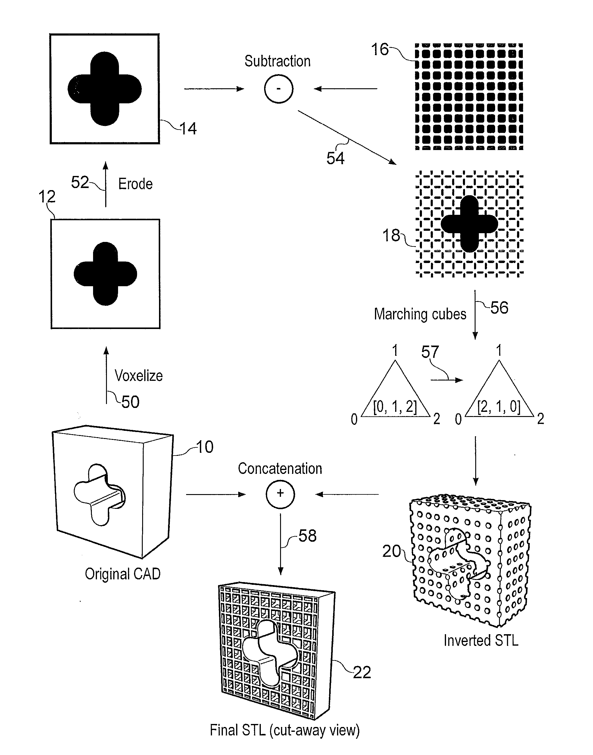
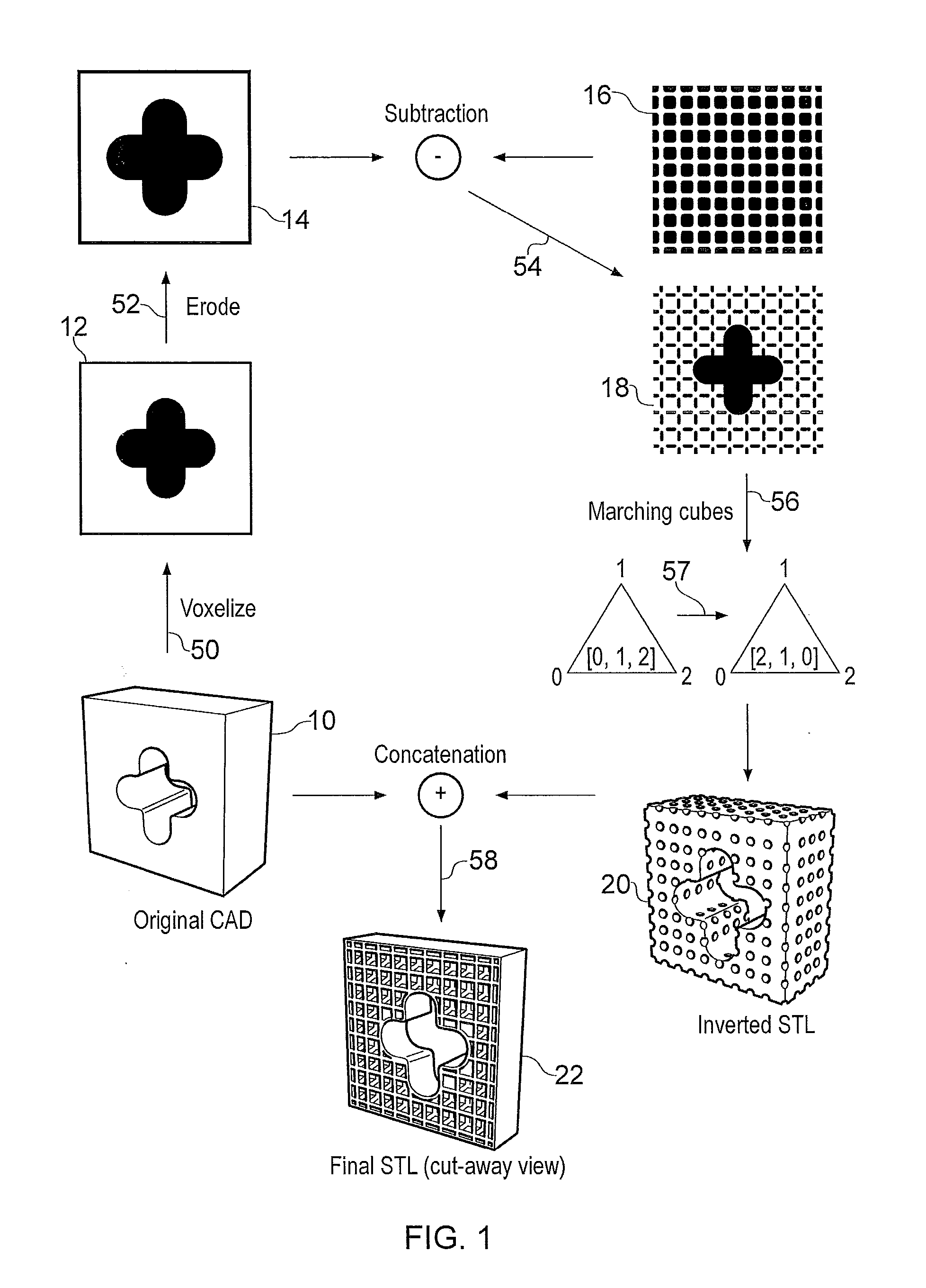
[0041]FIG. 1 illustrates a method that is an embodiment of the invention. The aim of this embodiment is to introduce into a solid (or filled) model an internal space, which internal space may have a microstructure, e.g. foam or the like.

[0042]The method starts from a vector-based representation of a three-dimensional model, which in this example is a perspective view of a cuboidal CAD model 10. A first step 50 in the method comprises converting the CAD model 10 into a three-dimensional image or digital representation 12. This can be carried out by sampling the volume enclosed by the CAD model 10. In effect the model is converted into a three-dimensional bitmapped image, e.g. each bit representing a voxel of the digital representation. For convenience in this example, the voxels in the digital representation 12 are shown as cuboidal, but other suitable shapes may be used.

[0043]The conversion of the CAD model 10 into the digital representation 12 is a lossy transformation. Detailed fe...


PUM

PropertyMeasurementUnit
Densityaaaaaaaaaa
Volumeaaaaaaaaaa
Microstructureaaaaaaaaaa

Abstract

A method for preparing image data for three-dimensional printing in which a digitised (e.g. voxelized) representation of a virtual three-dimensional object (e.g. CAD model) is eroded to create an internal volume for the object. Subsequently, a vector-based surface representation of this internal volume is generated and simply combined with a corresponding vector-based surface representation of the original virtual three-dimensional object to yield a hollowed out model in a format suitable for three-dimensional printing.A microstructure may be introduced into the interior of the hollowed out model, e.g. by extracting a volume corresponding to the inverse of that microstructure from the eroded digitised representation.

Description

[0001]This patent application claims the benefit of priority under 35 U.S.C. Section 119(e) from Great Britain Patent Application No. 1003065.8, filed on Feb. 23, 2010, now pending and entitled “Image Processing Method and Method of Three-Dimensional Printing Incorporating the Same”, which is hereby incorporated by reference in its entirety.FIELD OF THE INVENTION[0002]The invention relates to the preparation of image data for three-dimensional printing, e.g. for use in the manufacture of three-dimensional models in rapid prototyping apparatus or the like, where a three-dimensional model is built by successive deposition of a plurality of layers, e.g. using selective laser sintering and selective laser melting.BACKGROUND TO THE INVENTION[0003]It is known to build physical three-dimensional models using additive manufacturing technology. Typically, a virtual design of the three-dimensional model, e.g. represented through computer-aided design (CAD) software or the like, is transformed...

Claims


Application Information

Patent Timeline
IPC IPC(8): G06F3/12
CPCB29C67/0088G06F3/1208G06T19/20G06F3/1244G06T17/00G06F3/1219G06T2219/2021B29C64/386B33Y50/00G06F30/20G06F2113/10G06F2119/18Y02P90/02G06T15/00
Inventor YOUNG, PHILIPPE GEORGESRAYMONT, DAVID
Owner SYNOPSYS INC
Learn More