Ytterbium-doped optical fiber

a technology of ytterbium-doped optical fibers and ytterbium-doped fibers, applied in the direction of cladded optical fibers, instruments, optical elements, etc., can solve the problems of deterioration, loss of optical fiber output, loss of optical fibers, etc., to suppress the increase of the refractive index of the core, inhibit non-linear optical effects, and inhibit photodarkening and background loss

Active Publication Date: 2011-08-25
THE FUJIKURA CABLE WORKS LTD
View PDF5 Cites 5 Cited by
  • Summary
  • Abstract
  • Description
  • Claims
  • Application Information

AI Technical Summary

Benefits of technology

[0037]The ytterbium-doped optical fiber of the present invention includes a core containing at least ytterbium, aluminum and phosphorous and a clad surrounding the core, wherein a molar concentration of diphosphorus pentoxide with respect to phosphorus in the core is equal to a molar concentration of aluminum oxide with respect to aluminum in the core, wherein a ratio of the molar concentration of diphosphorus pentoxide with respect to phosphorus in the core to the molar concentration of ytterbium oxide with respect to ytterbium in the core is higher than or equal to 10 and lower than or equal to 30, wherein the relative refractive index difference between the core and the clad is higher than or equal to 0.05% and lower than or equal to 0.30%. For this reason, it is possible to realize an optical fiber capable of inhibiting photodarkening and background loss and at the same time, suppressing an increase in the refractive index of the core so that non-linear optical effects can be inhibited.

Problems solved by technology

When such transmission loss increases, the gain of the optical fiber, in which a rare-earth element is doped and which is an amplification media, deteriorates.
That is, the output of fiber-type optical amplifiers or fiber lasers is deteriorated over time, thus causing problems from the viewpoint of reliability.
As a result, problems, such as deterioration in the strength of the propagated laser output light and widening of the spectrum range of the laser light occur.
However, in accordance with the method disclosed in Non-Patent Document 1, photodarkening can be reliably inhibited, but cannot fundamentally realize sufficient dehydration.
For this reason, there is a problem in that the transmission loss caused by hydroxyl groups is great.
Further, the method has the difficulty of increasing the size of preforms and of a low yield.
Accordingly, the method is not good for reducing optical fiber manufacturing costs.
As a result, there is a problem in that the refractive index of the optical fiber core increases.
A small core diameter means that the effective core cross-sectional area (Aeff) of the optical fiber becomes small and thus the power density of the propagating light becomes high, whereby non-linear optical effects are liable to occur.
That is, wavelength conversion occurs due to the non-linear optical effects and there is a problem in that the desired output light cannot be obtained.
Accordingly, when an attempt is made to transmit light in single mode transmission or a low number of modes of transmission using the optical fiber obtained by this method, there is a problem in that the non-linear optical effects mentioned above readily occur.
There is a concern that photodarkening cannot be sufficiently inhibited simply by adding the elements to the core in the concentration range mentioned in Patent Document 1.

Method used


Image

  • Ytterbium-doped optical fiber
  • Ytterbium-doped optical fiber
  • Ytterbium-doped optical fiber

Examples


experimental example 1

[0092]Yb-doped optical fiber was prepared. The prepared Yb-doped optical fiber was a single clad fiber, which included a clad provided at the periphery of the core and a protective coating layer provided at the periphery of the clad.

[0093]The fiber preform was prepared by an MCVI) method, Further, ytterbium was added by a solution doping method. In addition, the protective coating layer was provided at the periphery of the clad by drawing the fiber preform until the outer diameter of the glass was adjusted to be about 125 μm.

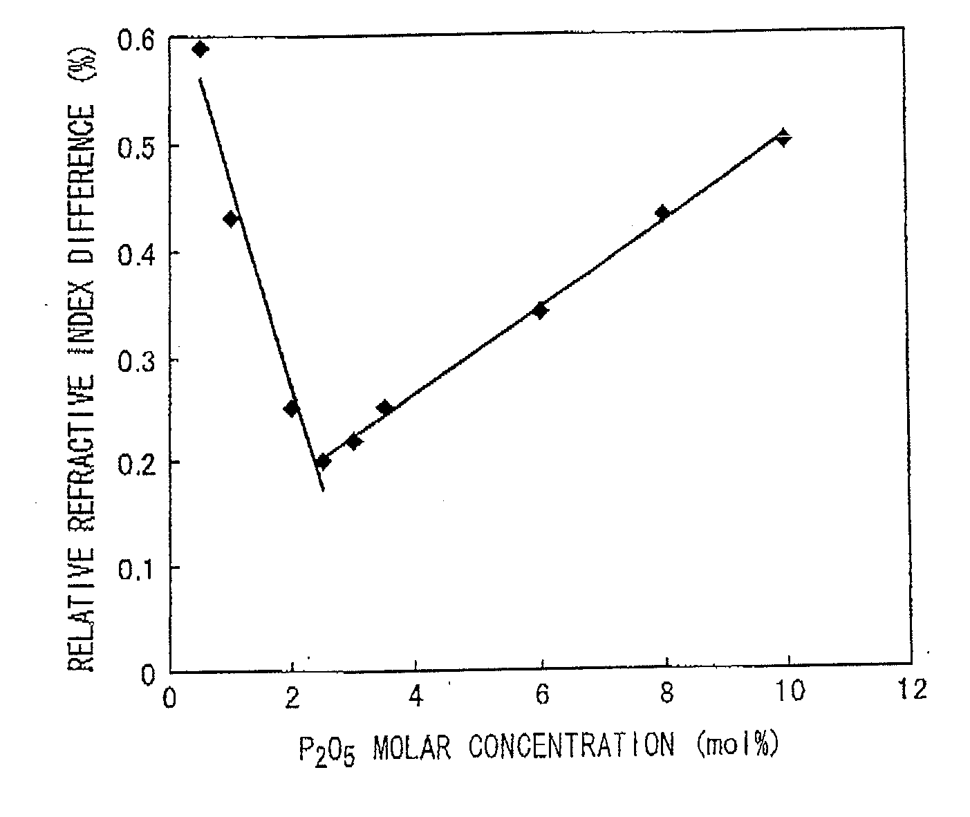
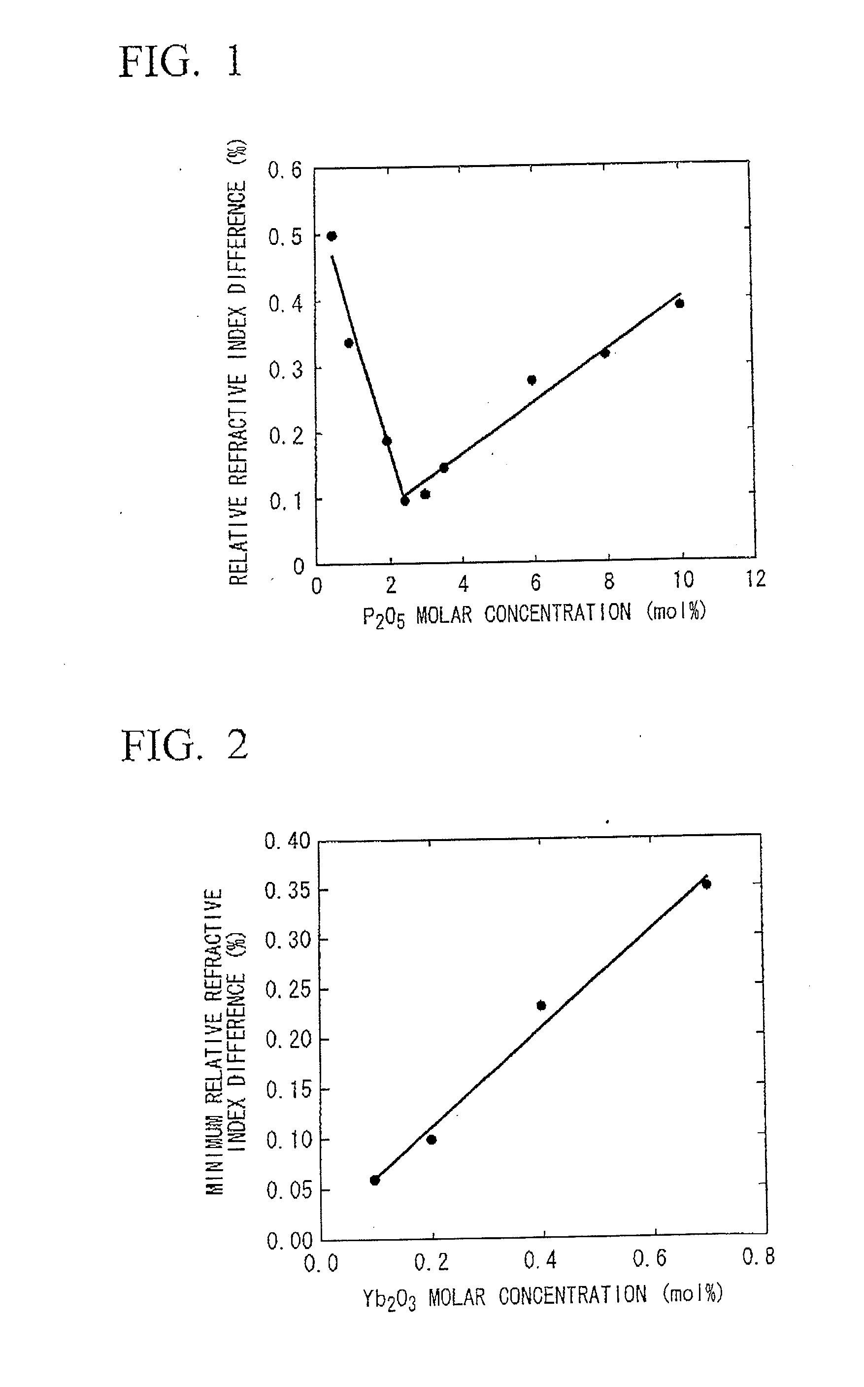
[0094]In the case where the molar concentration of ytterbium oxide (Yb2O3) in the core was maintained at 0.20 mol %, the molar concentration of aluminum oxide (Al2O3) in the core was maintained at 2.5 mol % and the molar concentration of diphosphorus pentoxide (P2O5) in the core was varied, the variation in relative refractive index difference (Δ) between the core and the clad for the Yb-doped optical fiber was obtained.

[0095]The results are shown in FIG. 1.

[009...

experimental example 2

[0098]The variation (Δ) in relative refractive index difference between the core and the clad for the Yb-doped optical fiber was obtained, in the case where the molar concentration of diphosphorus pentoxide (P2O5) in the core was varied, in the same manner as in Experimental Example 1 except that the molar concentration of ytterbium oxide (Yb2O3) in the core was maintained at 0.10 mol % and the molar concentration of aluminum oxide (Al2O3) in the core was maintained at 2.5 mol %, and was then shown in the type of graph as FIG. 1 (not illustrated).

[0099]From these results, it can be seen that, in the case where the molar concentration of diphosphorus pentoxide was about 2.5 mol %, which is substantially equal to the molar concentration of aluminum oxide, the relative refractive index difference between the core and the clad was a minimum. Further, in a region with a concentration higher than the molar concentration of diphosphorus pentoxide at which the relative refractive index diff...

experimental example 3

[0102]The variation (Δ) in relative refractive index difference between the core and the clad for the Yb-doped optical fiber was obtained, in the case where the molar concentration of diphosphorus pentoxide (P2O5) in the core was varied, in the same manner as in Experimental Example 1 except that the molar concentration of ytterbium oxide (Yb2O3) in the core was maintained at 0.40 mol % and the molar concentration of aluminum oxide (Al2O3) in the core was maintained at 5.0 mol %, and was then shown in the type of graph as FIG. 1 (not illustrated).

[0103]From these results, it can be seen that, in the case where the molar concentration of diphosphorus pentoxide was about 5.0 mol %, which is substantially equal to the molar concentration of aluminum oxide, the relative refractive index difference between the core and the clad was a minimum. Further, in a region with a concentration higher than the molar concentration of diphosphorus pentoxide at which the relative refractive index diff...


PUM

PropertyMeasurementUnit
oscillation wavelengthaaaaaaaaaa
refractive indexaaaaaaaaaa

Abstract

Provided is an ytterbium-doped optical fiber including a core containing at least ytterbium, aluminum and phosphorous and a clad surrounding the core, wherein a molar concentration of diphosphorus pentoxide with respect to phosphorus in the core is equal to a molar concentration of aluminum oxide with respect to aluminum in the core, wherein a ratio of a molar concentration of diphosphorus pentoxide with respect to phosphorus in the core to the molar concentration of ytterbium oxide with respect to ytterbium in the core is higher than or equal to 10 and lower than or equal to 30, and wherein a relative refractive index difference between the core and the clad is higher than or equal to 0.05% and lower than or equal to 0.30%.

Description

CROSS-REFERENCE TO RELATED APPLICATION[0001]This is a Continuation Application of International Application. No. PCT / JP2009 / 005862, filed on Nov. 4, 2009, which claims priority to Japanese Patent Application No. 2008-283165 filed on Nov. 4, 2008 and International Application No. PCT / JP2009 / 052064, filed on Feb. 6, 2009. The contents of the aforementioned applications are incorporated herein by reference.BACKGROUND OF THE INVENTION[0002]1. Field of the Invention[0003]The present invention relates to an ytterbium-doped optical fiber for light amplification to which ytterbium is doped. More specifically, the present invention relates to an ytterbium-doped optical fiber in which deterioration in output, known as “photodarkening”, and non-linear optical effects are inhibited.[0004]2. Description of the Related Art[0005]A fiber for light amplification has a configuration in which a rare-earth element or the like is doped to a core and / or a clad of an optical fiber having an axisymmetric w...

Claims


Application Information

Patent Timeline
Patent Type & Authority Applications(United States)
IPC IPC(8): G02B6/02
CPCH01S3/06716H01S3/06754C03C2201/28H01S3/1693H01S3/175H01S3/1618H01S3/06733H01S3/302
Inventor ICHII, KENTAROTANIGAWA, SHOJIARAI, TOMOFUMI
Owner THE FUJIKURA CABLE WORKS LTD
Why Eureka
Try Eureka