Air compressor

a compressor and air technology, applied in the direction of positive displacement liquid engines, pump control, motor parameters, etc., can solve the problems of significantly lowering affecting the and affecting the working efficiency of pneumatic tools. , to achieve the effect of improving the working efficiency of pneumatic tools and saving energy

Active Publication Date: 2011-08-25
HITACHI KOKI CO LTD
View PDF6 Cites 20 Cited by
  • Summary
  • Abstract
  • Description
  • Claims
  • Application Information

AI Technical Summary

Benefits of technology

[0027]The features of the invention make it possible to determine if the amount of consumption of compressed air in the air tank is large or small, and set the revolving speed of the electric motor for restoring compressed air according to the large / small amount of air consumption, thereby ensuring an energy-saving operation.
[0028]According to another feature of the invention, the forced operation of the electric motor at a constant revolving speed is carried out when the drop of air pressure in the air tank reaches to the minimum set pressure value corresponding to the use limit pressure of a pneumatic tool, so that the time for restoration of compressed air can be always set to a constant time. This can improve the working efficiency of using a pneumatic tool.

Problems solved by technology

However, when the conventional air compressor as mentioned above is used to continuously use a pneumatic tool, as shown in FIG. 6B, the air pressure in the air tank drops to or below the use limit pressure of the pneumatic tool due to the insufficient capacity of the air compressor to generate compressed air.
As a result, a worker should interrupt the operation of the pneumatic tool.
When such a situation occurs, the worker interrupts the work with the pneumatic tool, and performs another work, such as set-up work, raising a problem of significantly lowering the working efficiency with the pneumatic tool.
According to the conventional another control system of changing the revolving speed of the electric motor of the air compressor to a high revolving speed or a low revolving speed, when the low-speed operation is selected for an energy-saving operation, the restoration time always become long.
Accordingly, the restoration time becomes long for the workable quantity of a nailing machine or the like, raising a problem of significantly impairing the working efficiency.

Method used


Image

  • Air compressor
  • Air compressor
  • Air compressor

Examples


Embodiment Construction

[0036]An embodiment of the present invention will be hereinafter described with reference to FIGS. 1 to 6. In all the diagrams illustrating the embodiment, common reference numerals are given to members having the same functions or elements to avoid their redundant descriptions.

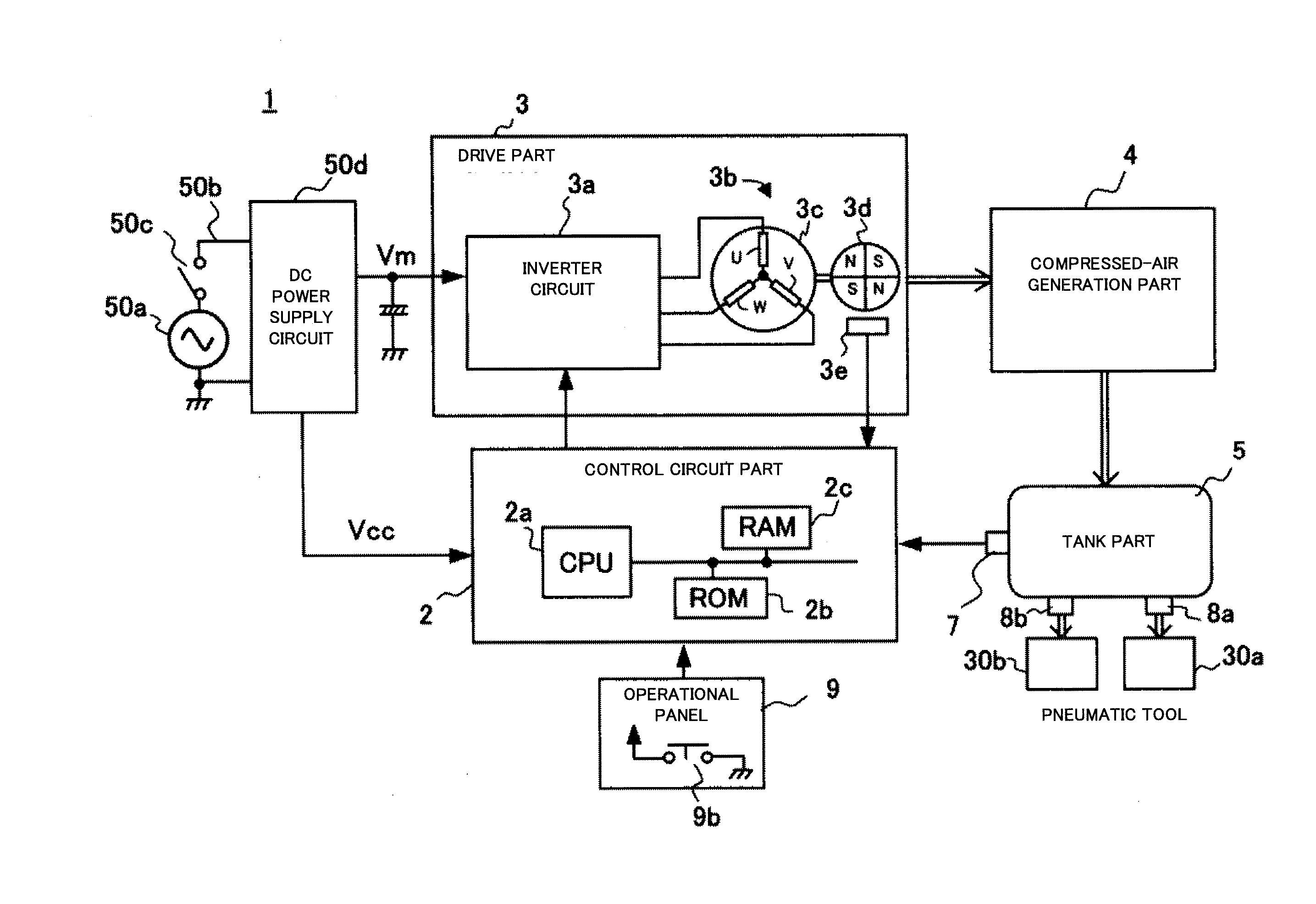
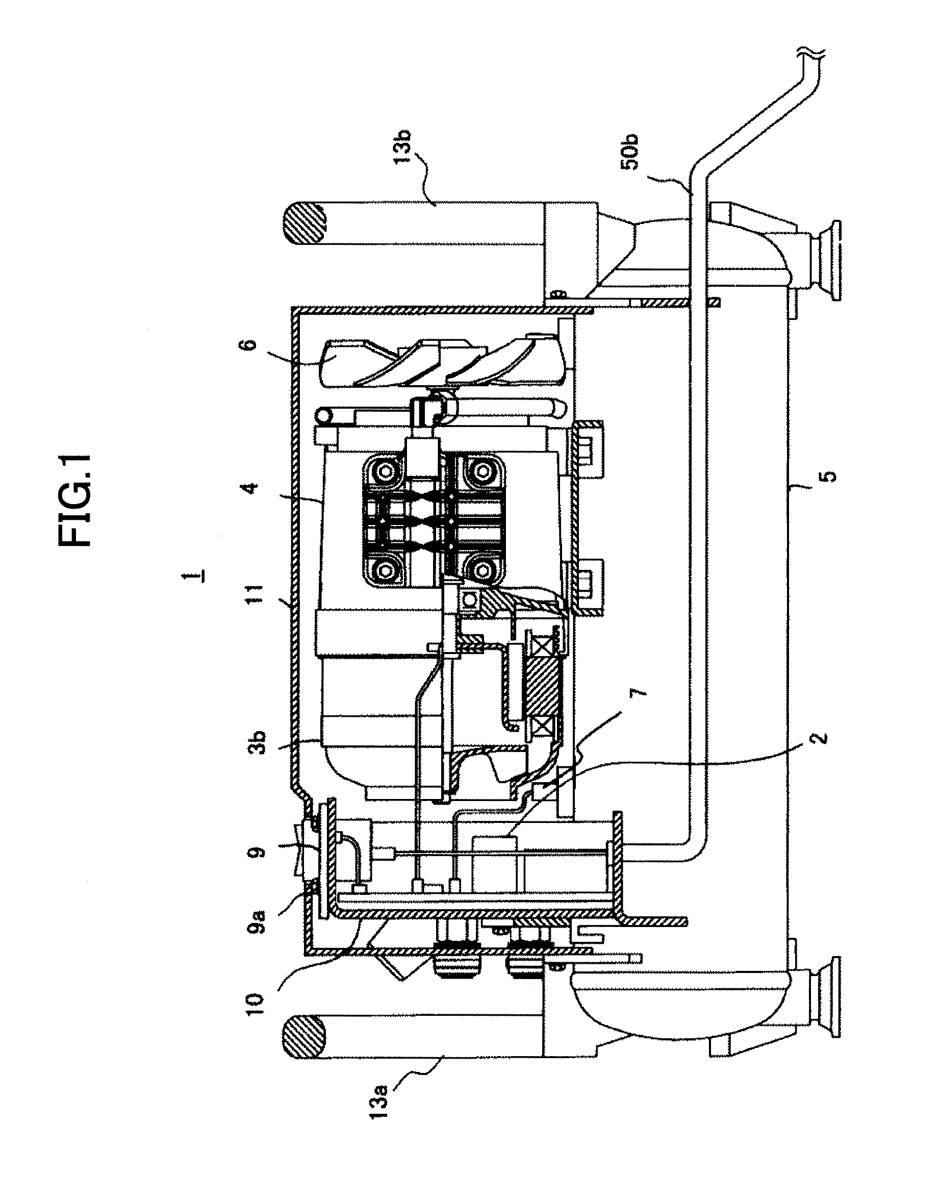
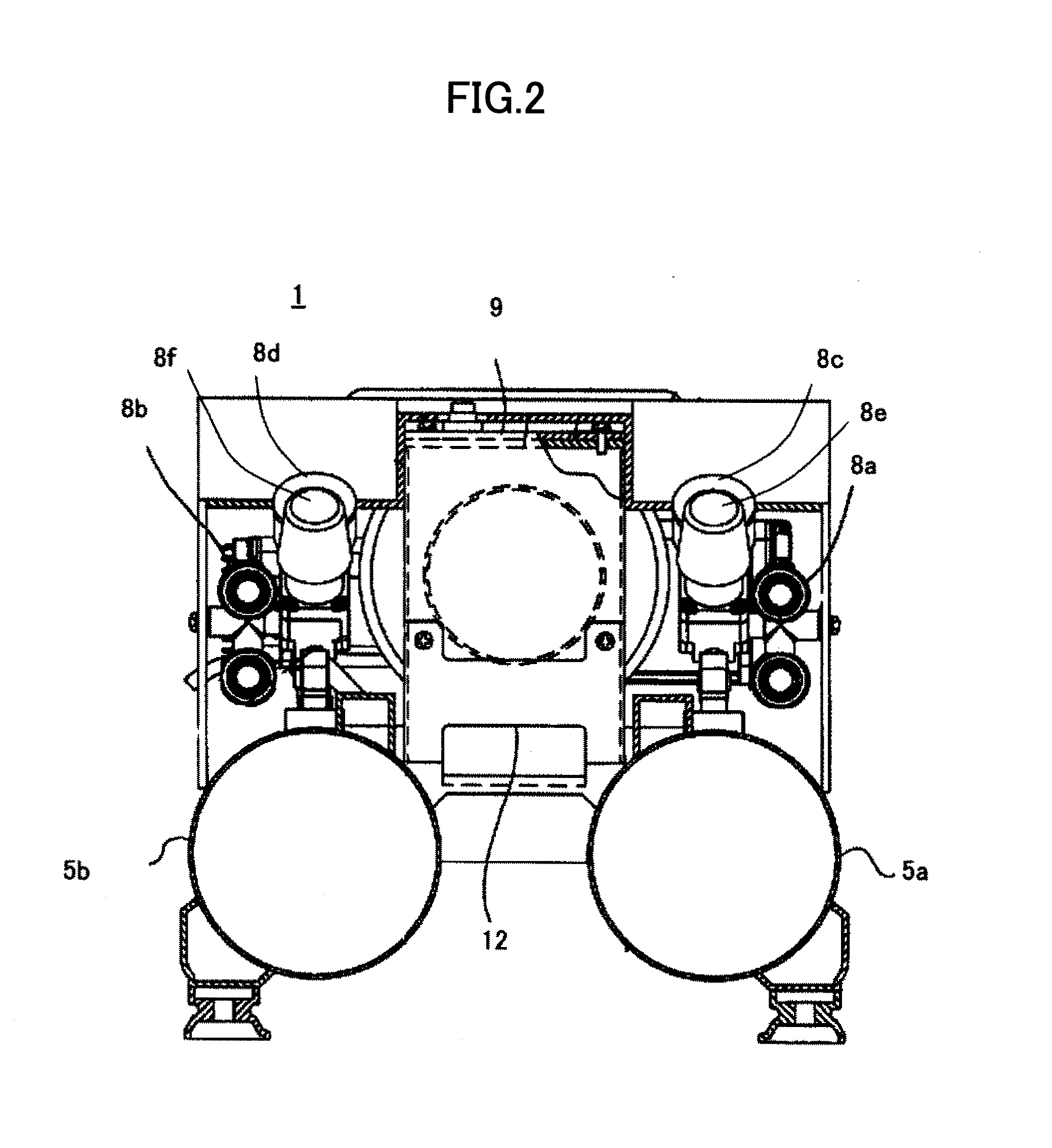
[0037]FIG. 1 and FIG. 2 show diagrams of the external appearance of an air compressor 1 according to this embodiment, and FIG. 3 shows a system block diagram of the air compressor 1.

[0038]As shown in FIG. 1, the air compressor 1 has a tank part 5 including a pair of tanks 5a and 5b formed in an elongated cylindrical shape for storing compressed air, a pressure sensor 7 (see FIG. 3) for detecting an air pressure inside the tanks 5a, 5b, a compressed-air generation part 4 which generates compressed air and supplies the compressed air to the tank part 5, a drive part 3 including an electric motor 3b for driving the compressed-air generation part 4, a control circuit part 2 disposed inside a cover 11 to control t...


PUM


Abstract

When an air pressure in a tank part (5) drops from a maximum set pressure value (A1) to or below at least one restart set pressure value defined to lie in a range between the maximum set pressure value and a minimum set pressure value, a control circuit part (2) operates an electric motor (3b) at a predetermined revolving speed. When the air pressure in the tank part (5) drops from the restart set pressure value to or below the minimum set pressure value, the control circuit part (2) operates the electric motor (3b) at the predetermined revolving speed or a revolving speed lower than N2 until the air pressure in the tank part (5) reaches the maximum set pressure value.

Description

TECHNICAL FIELD [0001]The present invention relates to an air compressor which generates compressed air to drive a pneumatic tool, such as a nailing machine.BACKGROUND ART[0002]Generally, an air compressor to be used for a pneumatic tool converts the rotary motion of an electric motor into the reciprocating motion of a piston inside a cylinder via a crankshaft, compresses air sucked in from a suction valve by the reciprocating motion of the piston, and stores the compressed air in an air tank part from an exhaust valve of the cylinder, as disclosed in Patent Document 1 mentioned below. This air compressor is carried together with a pneumatic tool into a work site, such as a construction site. Then, the air compressor is used as a drive source to drive a nail or screw into a work member like a lumber by supplying the compressed air stored in the air tank part of the air compressor to a pneumatic tool (e.g., nailing machine) via an air hose.[0003]As this air compressor is carried toge...

Claims


Application Information

Patent Timeline
Patent Type & Authority Applications(United States)
IPC IPC(8): F04B49/00
CPCF04B41/02F04B49/00F04B2205/05F04B49/065F04B2203/0209F04B49/022
Inventor YOKOTA, TOMOYOSHIKODATO, SEIICHIMATSUNAGA, KENICHI
Owner HITACHI KOKI CO LTD
Why Eureka
Try Eureka