
Sealed battery

a battery and seal technology, applied in the field of sealable batteries, can solve the problems of particularly undesirable increase in internal resistance, and achieve the effects of facilitating the rupture, preventing battery and adverse environment effects, and facilitating the ruptur

Active Publication Date: 2011-08-25
TOYOTA JIDOSHA KK
View PDF9 Cites 15 Cited by
  • Summary
  • Abstract
  • Description
  • Claims
  • Application Information

AI Technical Summary

Benefits of technology

[0010]The present invention has been created with the foregoing in view and it is a main object of the invention to provide a sealed battery including a current cut-off mechanism that can reliably cut off the current in the abnormal state and has a structure that makes it possible to discharge a comparatively large current, while preventing the increase (rise) in internal resistance in the normal state.
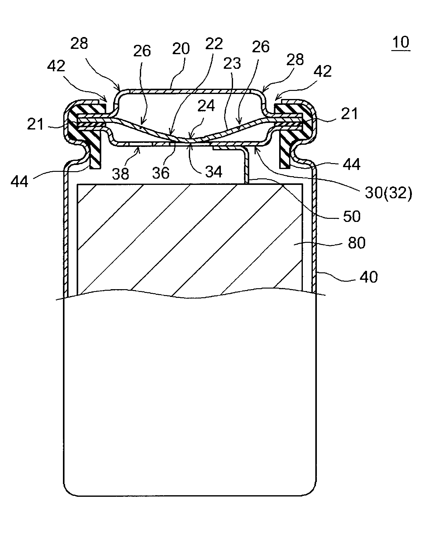
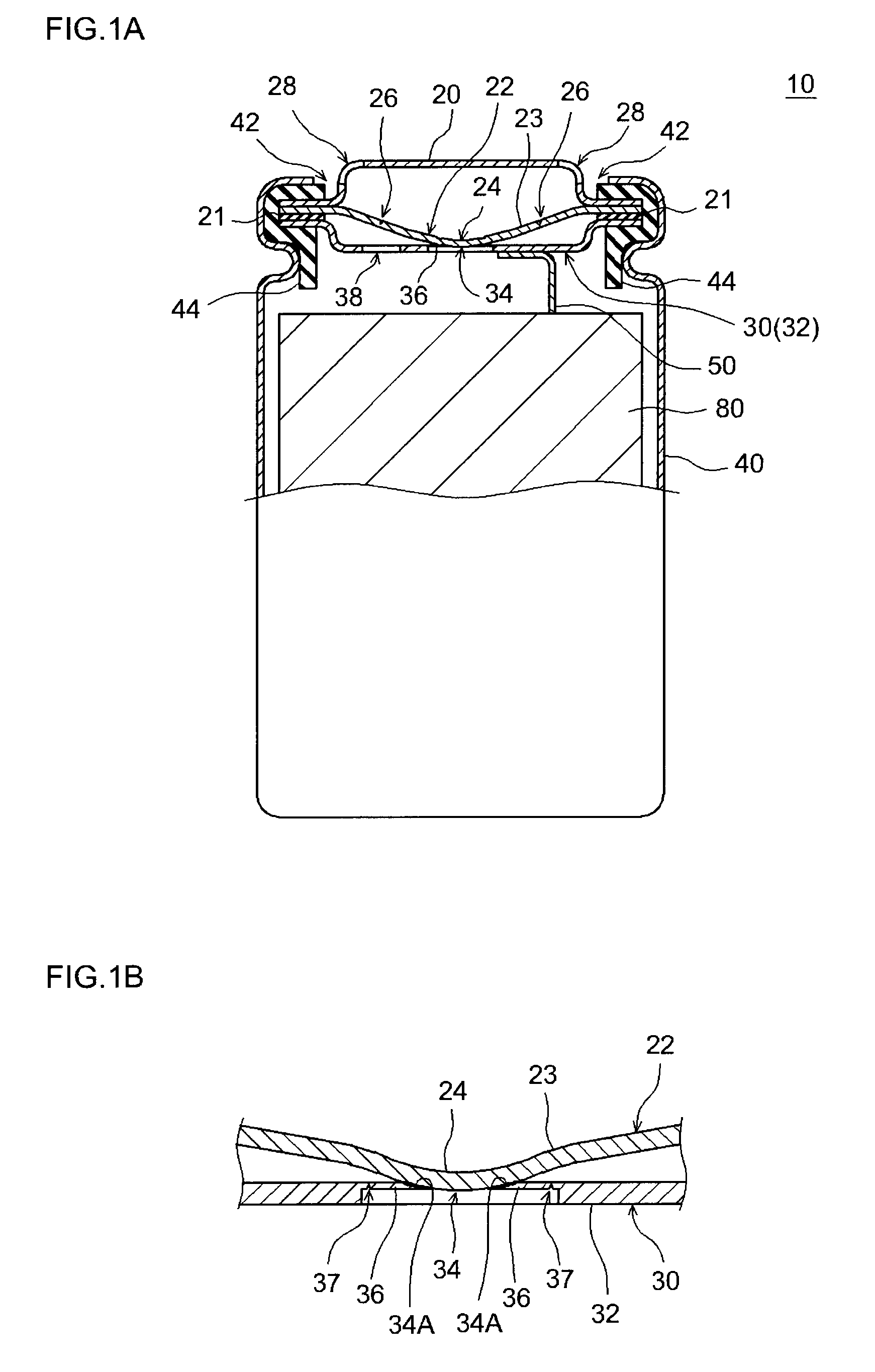
[0025]In the cylindrical battery of such an embodiment, the central portion of the disk-shaped current cut-off valve is fitted into the engagement hole provided in the central portion of the disk-shaped connecting member (typically, a conductive member linked to the electrode body located inside the case of the lead member from the electrode body), and the peripheral edge of the engagement hole and the circumference of the fitted portion of the current cut-off valve are linearly (annularly) joined. Alternatively, the inner wall of the engagement portion and the portion of the fitted portion of the current cut-off valve that is in contact with the inner wall are joined over a surface (an annularly expanding surface of the inner wall of the engagement hole). Therefore, it is possible to provide a sealed battery having a current cut-off mechanism that is suitable for conduction of a comparatively large current, without increasing the internal resistance.

Problems solved by technology

Such increase in internal resistance is especially undesirable in batteries for vehicles that are discharged by a large current.

Method used


Image

  • Sealed battery
  • Sealed battery
  • Sealed battery

Examples


Embodiment Construction

[0033]A preferred embodiment of the present invention will be described below with reference to the appended drawings. A matter necessary for implementing the invention (for example, a joining method such as welding, configurations of the electrode body and electrolytic solution constituting the battery, processes for constructing the battery) that are not the matter particularly referred to in the present description (for example, a joint structure of the connecting member and current cut-off valve) can be construed as a design matter to be selected as appropriate by a person skilled in the art on the basis of the conventional techniques and configurations in the related field. The present invention can be implemented on the basis of the contents disclosed in the present description and the common technical knowledge in the related field.

[0034]The sealed battery provided by the present invention includes the current cut-off valve and the connecting member joined by the aforemention...


PUM


Abstract

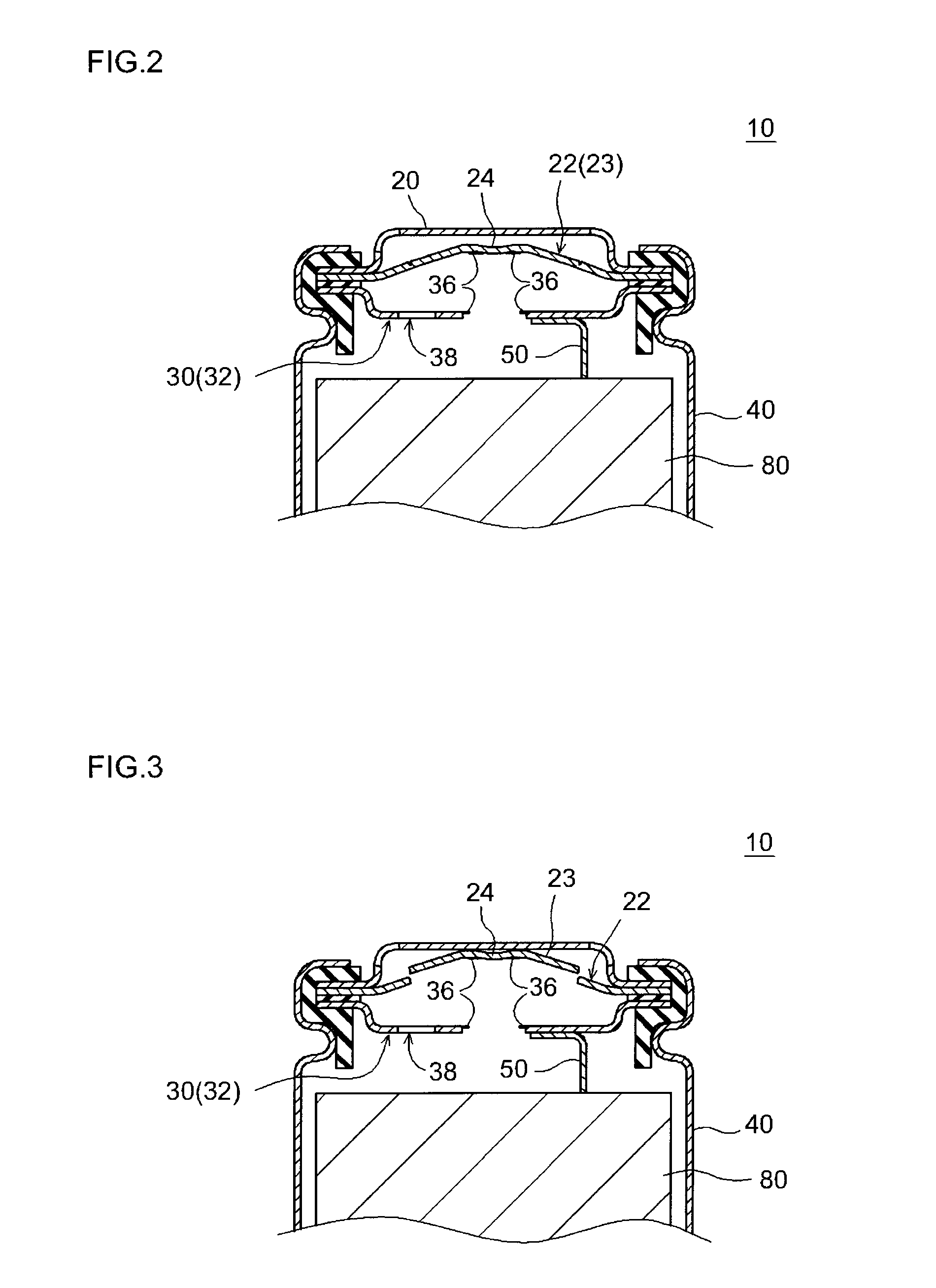
A sealed battery (10) provided by the present invention includes: a current cut-off valve (22); and a connecting member (30) having an engagement hole (34) formed in a location adjacent to the current cut-off valve. The current cut-off valve is conductively connected to the connecting member by joining linearly to a peripheral edge of the engagement hole and / or joining at a surface that is in contact with an inner wall of the engagement hole in a state in which part of the current cut-off valve is fitted into the engagement hole. When an internal pressure of a battery case (40) rises above a predetermined level, the current cut-off valve is deformed outward of the case by the internal pressure, the current cut-off valve is separated from the connecting member, and the electric connection between the connecting member and the current cut-off valve is broken.

Description

TECHNICAL FIELD[0001]The present invention relates to a sealed battery, and more particularly to a sealed battery provided with a current cut-off mechanism that cuts off the electric current at the time of abnormality.[0002]The present application claims priority to Japanese Patent Application No. 2008-285086 filed on Nov. 6, 2008, the contents of which is hereby incorporated by reference into the present application.BACKGROUND ART[0003]Secondary batteries (storage batteries) such as lithium ion batteries and nickel hydride batteries have recently gained importance as power sources for installation on vehicles or power sources for personal computers and portable terminals. In particular, lightweight lithium ion batteries that make it possible to obtain a high energy density are expected to be advantageously used as high-power power sources for installation on vehicles. Examples of typical structures of such secondary batteries include batteries of sealed structure (sealed batteries)...

Claims


Application Information

Patent Timeline
IPC IPC(8): H01M2/34H01M2/12
CPCH01M2200/00H01M2200/20Y02E60/10H01M50/3425H01M50/578H01M2220/20H01M50/574H01M50/147H01M50/152H01M50/171H01M50/572H01M50/531H01M50/30H01M10/052
Inventor KIYAMA, AKIRAYAMADA, TADAYOSHI
Owner TOYOTA JIDOSHA KK
Learn More